T-375
2–10
2.5 Battery and Battery Charging System
The battery provides 12 VDC power to the starter motor. It also provides the initial voltage for the Intake Heater
until the unit starts.
The solid state battery charger is located in front of the battery. The battery charger is powered by the generator,
and this input is protected by fuses located in the receptacle box. The battery charger produces a tapered charge
(40 amps maximum) and is designed not to overcharge the battery.
CAUTION
!
Observe proper polarity when installing the battery or connecting a battery charger. The nega
-
tive battery terminal must be grounded. Reverse polarity may damage the charging system.
When charging the battery in unit, isolate the battery by disconnecting the negative battery ter
-
minal first, then the positive. Once the battery has been charged, connect the positive battery
terminal first, then the negative.
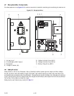
2.6 Control Panel and Control Box Components
The control panel and control box (see
) contain components required for monitoring and controlling the
Genset unit.
2.6.1
Water Temperature Gauge
The Water Temperature Gauge observes water operating temperature. Once the unit has achieved normal running
temperature, the coolant temperature is between 82 - 96°C. The Water Temperature Sensor senses engine water
temperature and transmits a signal to the Water Temperature Gauge.
2.6.2
Oil Pressure Gauge
The Oil Pressure Gauge observes normal operating engine oil pressure. Normal oil pressure is 3.3 to 5.2 kg/cm2.
), located at the oil filter housing, senses lube oil pressure and transmits a
signal to the Oil Pressure Gauge.
2.6.3
Total Time Meter (TT)
The Total Time Meter (TT) calculates the total hours the unit has been running, which provides an accurate readout
of accumulated engine running time. This data can be used to establish proper maintenance schedules (refer to
).
2.6.4
Ammeter (A)
The Ammeter indicates the rate of charge or discharge of the battery charging system. The battery charging
system is composed of the battery and the battery charger, either solid state or alternator. During start up, the
intake heater draws approximately 42 amps.
2.6.5
Intake Heater Switch (HS)
The Intake Heater Switch (HS) is a momentary switch. When held in the PREHEAT position, the switch allows
approximately 42 amps of battery current to flow into the intake heater, which preheats the air within the intake
manifold and allows the engine to start. After starting the engine, the intake heater switch should continue to be
held in the ON position for approximately 5 seconds until the engine has developed enough oil pressure to close
the oil pressure safety switch.
2.6.6
Ignition Switch (IGN)
The Ignition Switch (IGN) is a momentary switch that has OFF/ON/START positions. When held in the START
(ignition) position, it energizes the starter motor solenoid, which in turn allows the starter motor to crank the engine.
The switch is released to the RUN position once the engine has started.
2.6.7
Intake Heater Timer (IHT)
The Intake Heater Timer (IHT) continues to supply power to the intake heater for 3 minutes after initial start-up.
2.6.8
Starter Solenoid Timer (SST)
The Starter Solenoid Timer (SST) limits the amount of time that the starter can be engaged to 15 seconds. If the
starter is manually engaged for more than 15 seconds, power will be cut to the starter. Once power has been
removed, the starter can again be engaged for up to 15 seconds.
Summary of Contents for 69UG15
Page 2: ......
Page 4: ......
Page 12: ......
Page 32: ......
Page 40: ......
Page 58: ......
Page 60: ...T 375 6 2 Figure 6 2 Schematic for 12 VDC Control Circuit 12 VDC Control Circuit ...
Page 61: ...6 3 T 375 Figure 6 3 Schematic High Voltage Circuitry High Voltage Circuitry Receptacle Box ...
Page 62: ......
Page 65: ......


