5–7
T-375
CAUTION
!
Do not underfill or overfill the oil bath cups. Overfilling cups causes loss of capacity; underfill
-
ing cups causes lack of filtering efficiency.
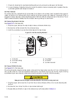
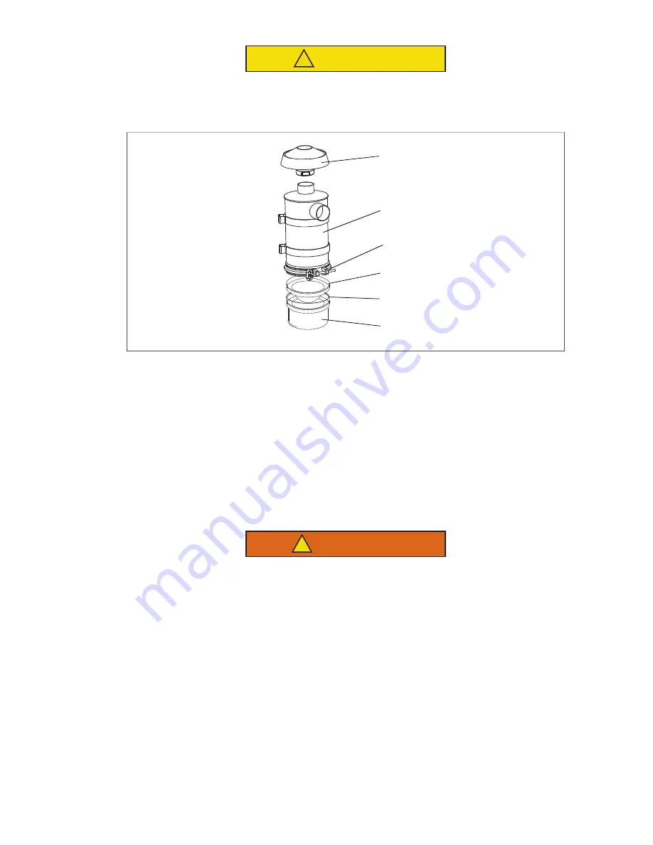
Figure 5.3 Air Cleaner, Oil Bath
1) Air Inlet Hood
2) Air Cleaner Body
3) Cap Clamp
4) Inner Oil Cup
5) Gasket
6) Oil Cup
- - - - -
Air Cleaner Body Service
The air cleaner body should be inspected each time the oil cup is serviced. If there is any sign of contaminant
buildup or plugging, the air cleaner body should be removed and back flushed.
At least once a year, or at regular engine service intervals, remove the entire air cleaner and perform the following
cleaning procedure:
1. Remove oil cup. Check and clean center tube.
WARNING
!
Do not use gasoline to clean air cleaner parts.
2. Pump solvent through the air outlet with sufficient force and volume to produce a hard, even stream out of
the bottom of the body assembly. Reverse flush until all foreign material is removed.
1
2
3
4
5
6
Summary of Contents for 69UG15
Page 2: ......
Page 4: ......
Page 12: ......
Page 32: ......
Page 40: ......
Page 58: ......
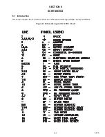
Page 60: ...T 375 6 2 Figure 6 2 Schematic for 12 VDC Control Circuit 12 VDC Control Circuit ...
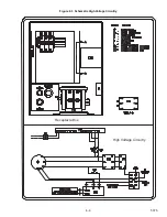
Page 61: ...6 3 T 375 Figure 6 3 Schematic High Voltage Circuitry High Voltage Circuitry Receptacle Box ...
Page 62: ......
Page 65: ......

