T-375
5–10
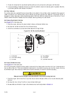
12. Back off about 25mm, but do not remove the engine shockmount bolts. This will allow the engine / generator
to be slightly lifted off of the unit frame.
NOTICE
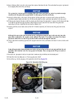
The generator / engine must be slightly lifted off of the unit frame in order to provide enough
clearance for the generator support plate to slide away from the unit frame.
13. Using the lifting lugs on the top of the generator, lift the generator / engine several inches so that the
generator support plate will clear the unit frame allowing the entire generator assembly to be removed.
14. Place several support beams under the engine and then lower the generator / engine onto the beams. Make
sure that the generator support plate is lifted high enough to allow for the removal of the generator
assembly, but not so high that the fan hits the radiator coil.
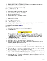
15. Starting with the lower bolts, remove the 3/8”-16 bolts / washers (12) that secure the generator to the
engine.
NOTICE
Although the generator torsional dampener and flywheel adapter plate will normally keep the
generator coupled to the engine, even without the bolts, it is safest to remove the lower
generator bolts first, in case the generator shifts and falls during bolt removal.
16. Lift the generator assembly (generator & support plate) off of the unit frame and lower it onto a stable work
surface.
NOTICE
Inspect the generator torsional dampener, bolt, and key as they will have to be removed from the old
generator and installed onto the new generator. Replace these components if they are worn or
damaged.
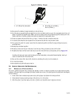
17. Remove the generator torsional coupler bolt / washer and pull off the torsional dampener.
18. Place the torsional dampener on the new generator shaft.
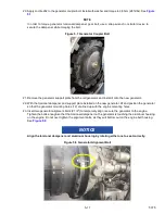
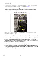
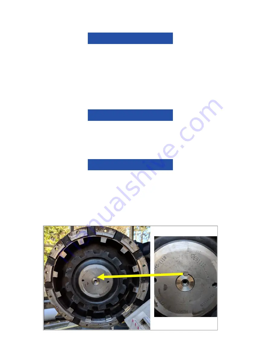
19. Insert the key into the keyway of the generator shaft. See
Figure 5.6 Generator Shaft Keyway
Summary of Contents for 69UG15
Page 2: ......
Page 4: ......
Page 12: ......
Page 32: ......
Page 40: ......
Page 58: ......
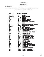
Page 60: ...T 375 6 2 Figure 6 2 Schematic for 12 VDC Control Circuit 12 VDC Control Circuit ...
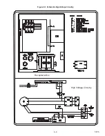
Page 61: ...6 3 T 375 Figure 6 3 Schematic High Voltage Circuitry High Voltage Circuitry Receptacle Box ...
Page 62: ......
Page 65: ......


