5–15
T-375
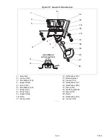
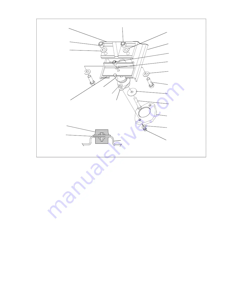
Figure 5.11 Generator Shockmounts
1) Generator
2) Locknut (5/8)
3) Flat Washer (5/8)
4) Support Plate
5) Screw (3/8)
6) Flat Washer (3/8)
7) Shockmount
8) Shockmount
9) Support Plate
10) Frame
11) Locknut (5/8)
12) Flat Washer (5/8)
13) Mounting Base
14) Locknut (1/2)
15) Flat Washer (1/2)
16) Flat Washer (5/8)
17) Screw (5/8)
18) Snubbing Washer
19) Screw (1/2)
20) Frame
21) Flat Washer (3/8)
22) Locknut (3/8)
- - - - -
1
17
10
13
20
16
11
14
15
7
4
18
19
5
21
22
Install Mount
with Large Flare
at Top
2
12
3
8
9
6
Summary of Contents for 69UG15
Page 2: ......
Page 4: ......
Page 12: ......
Page 32: ......
Page 40: ......
Page 58: ......
Page 60: ...T 375 6 2 Figure 6 2 Schematic for 12 VDC Control Circuit 12 VDC Control Circuit ...
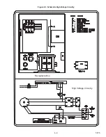
Page 61: ...6 3 T 375 Figure 6 3 Schematic High Voltage Circuitry High Voltage Circuitry Receptacle Box ...
Page 62: ......
Page 65: ......

