T-375
Index - 2
Isolators/Shockmounts Check and Replace
L
Low Oil Pressure Switch (LOP) Operation
M
Maintenance Precautions
O
Oil Pressure Gauge
Operating Precautions
P
Painted Surfaces
Poly V-belt Service
Post-Start Inspection
Pre-Start Inspection
Preventative Maintenance Schedule
R
Receptacle Box
S
Safety Devices
Safety Relay (S) Operation
Safety Summary
Schematic Diagram
Schematic Diagram - Legend
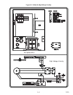
Schematic High Voltage Circuitry
Schematics
Sequence of Operation
Standard Mount Mounting
Starter Motor (SM) Operation
Starter Solenoid (SS) Operation
Starter Solenoid Timer (SST)
Starting and Stopping Instructions
Starting Instructions
Stopping Instructions
T
Total Time Meter (TT)
Truss and Isolator
U
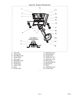
Unidrive Assembly Components
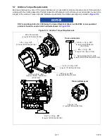
UniDrive Torque Requirements
Unit Nameplate
Unit Specifications
V
Voltage Controller (VC)
W
Water Temperature Gauge
Summary of Contents for 69UG15
Page 2: ......
Page 4: ......
Page 12: ......
Page 32: ......
Page 40: ......
Page 58: ......
Page 60: ...T 375 6 2 Figure 6 2 Schematic for 12 VDC Control Circuit 12 VDC Control Circuit ...
Page 61: ...6 3 T 375 Figure 6 3 Schematic High Voltage Circuitry High Voltage Circuitry Receptacle Box ...
Page 62: ......
Page 65: ......

