T-375
2–12
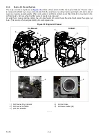
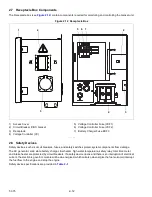
2.7 Receptacle Box Components
) contain components required for monitoring and controlling the Genset unit.
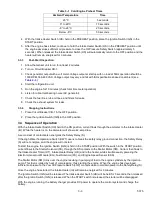
Figure 2.12 Receptacle Box
1) Access Cover
2) Circuit Breaker (CB1) Genset
3) Receptacle
4) Voltage Controller (VC)
5) Voltage Controller Fuse (VCF1)
6) Voltage Controller Fuse (VCF2)
7) Battery Charger Fuse BCF3
- - - - -
2.8 Safety Devices
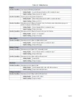
Safety devices, such as circuit breakers, fuses, and safety switches protect system components from damage.
The AC generator, solid state battery charger, fuel heater, high water temperature, safety relay, total time meter
and intake heater are protected by circuit breakers. If a safety device opens and there is an interruption of electrical
current, the electronic governor module will be de-energized, which will also de-energize the fuel solenoid, interrupt
the fuel flow to the engine and stop the engine.
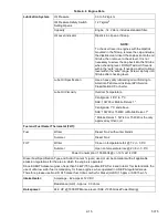
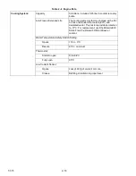
Safety device specifications are provided in
1
2
3
5 6 7
4
2
3
Summary of Contents for 69UG15
Page 2: ......
Page 4: ......
Page 12: ......
Page 32: ......
Page 40: ......
Page 58: ......
Page 60: ...T 375 6 2 Figure 6 2 Schematic for 12 VDC Control Circuit 12 VDC Control Circuit ...
Page 61: ...6 3 T 375 Figure 6 3 Schematic High Voltage Circuitry High Voltage Circuitry Receptacle Box ...
Page 62: ......
Page 65: ......


