5–1
T-375
SECTION 5
SERVICE AND PREVENTATIVE MAINTENANCE
5.1 Introduction
This section covers service for the generator set and general engine service. Refer to the Kubota engine workshop
, Section 1.1, for additional engine servicing.
WARNING
!
Beware of moving poly V-belt, belt driven components and hot exhaust components.
5.2 Preventative Maintenance Schedule
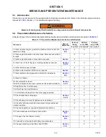
A tabular listing of the recommended preventative maintenance activities and schedule is provided in
Table 5–1 Preventative Maintenance Actions and Schedule
Procedure
Manual
Reference
Perform
During
Pre-Trip
1
Perform
every 2000
hrs service
2
Perform
every 4000
hrs service
3
1. Check (in place) engine / generator shockmounts for cracks, cuts,
abrasion or flaring
X
X
2. Check engine lubrication oil and fuel lines, filters and connections
for leaks.
-
X
X
X
3. Check engine lubrication oil level, add as required.
X
4. Check Poly V-belt for fraying or cracking, replace as required.
X
X
X
5. Check radiator hoses for leaks.
-
X
X
X
6. Check coolant level add 50/50 mix as required.
X
X
X
7. Check radiator coil and generator air intake for cleanliness.
X
X
X
8. Check Air Cleaner:
X
X
X
For Dry element air cleaner:
Check for cleanliness and clean / replace as filter indicator indicates
X
X
X
9. Drain Water from fuel tank sump.
-
X
X
X
10. Drain Water from fuel filter bowl.
-
X
X
X
11. Fill fuel tank with diesel fuel, check fuel gauge operation.
-
X
X
X
12. Check intake heater amperage.
X
X
X
13. Check battery terminals for tightness and cleanliness.
-
X
X
X
14. Check for dirty loose electrical connections, frayed cables and
cracked insulation.
-
X
X
X
15. Check and tighten as required all hardware, brackets etc.
-
X
X
X
16. Clean mechanical fuel lift pump internal filter.
X
X
17. Change in line fuel strainer (option).
X
X
18. Clean and coat terminals with battery terminal sealant.
-
X
X
19. Change lubricating oil and filters (See NOTES)
X
X
Summary of Contents for 69UG15
Page 2: ......
Page 4: ......
Page 12: ......
Page 32: ......
Page 40: ......
Page 58: ......
Page 60: ...T 375 6 2 Figure 6 2 Schematic for 12 VDC Control Circuit 12 VDC Control Circuit ...
Page 61: ...6 3 T 375 Figure 6 3 Schematic High Voltage Circuitry High Voltage Circuitry Receptacle Box ...
Page 62: ......
Page 65: ......

