5–13
T-375
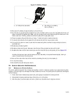
Figure 5.10 Battery Charger
1) AC Wiring from Generator
2) DC Wiring to 12v Battery
Red (+), Black (-)
- - - - -
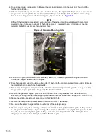
34. Re-secure the battery charger assembly to the unit frame.
35. Cut the wire-tie supporting the receptacle box to the unit frame and re-secure the receptacle box to the unit
frame using bolts and washers (6). Make sure the receptacle wires are pulled through the access port in the
frame and ensure that they will be accessible to splice with the generator wires.
36. Place two pieces of heat shrink tubing (1 large, 1 small) over each receptacle box wire.
37. Connect and butt splice the receptacle box harness wires with the new generator wires.
38. For each of the other five wires, heat shrink the small tubing first, and then the large tubing to ensure a
watertight seal.
39. Neatly tape all wires together.
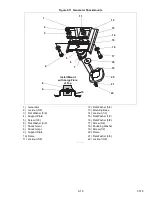
40. Replace and secure the wire harnesses onto the top of the generator, secure with the bolt.
41. Replace the truss and the truss brackets, secure the sides with the mounting bolts (2). See
.
NOTE
Installing the two back truss bolts first allows the truss assembly to be pulled forward slightly, making it
easier to install the two front truss bolts.
42. Secure the center of the truss to the isolator by installing the nuts (2) and nut plate (1).
43. Connect the battery.
44. Re-install the top and side panel covers.
5.6 General Generator Set Maintenance
5.6.1
Maintenance of Painted Surfaces
The unit is protected against the corrosive atmosphere in which it normally operates by a special paint system.
However, if the paint system is damaged, the base metal can corrode. If the paint system is scratched or damaged,
do the following:
1. Clean area to bare metal using a wire brush, emery paper or equivalent cleaning method.
2. Immediately following cleaning, spray or brush on a zinc rich primer.
3. After the primer has dried, spray or brush on finish coat of paint to match original unit color.
1
2
Summary of Contents for 69UG15
Page 2: ......
Page 4: ......
Page 12: ......
Page 32: ......
Page 40: ......
Page 58: ......
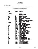
Page 60: ...T 375 6 2 Figure 6 2 Schematic for 12 VDC Control Circuit 12 VDC Control Circuit ...
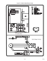
Page 61: ...6 3 T 375 Figure 6 3 Schematic High Voltage Circuitry High Voltage Circuitry Receptacle Box ...
Page 62: ......
Page 65: ......

