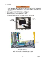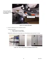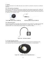
b. Mark the three mounting holes.
c. Remove the plate and prepare to drill the holes from the outside of the control box.
d. Drill three 0.397” (Drill size X) holes in the bottom of the control box. Remove any burrs from
drilling out of the control box.
e. Install three Rivnuts (34-06051-104) into the three holes.
f.
Attach the mounting plate to the control box using three 34-01341-25 bolt
g. Install the eSolutions module to the mounting plate on the bottom of the control box using three
M5 Nylock nuts (34-01184-05) and flat washers (34-00944-05).
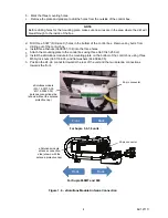
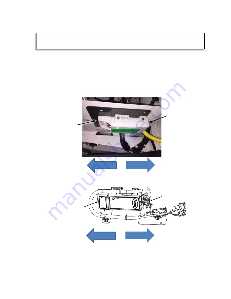
h. Position the 24-pin connector towards the rear of the unit and the two antenna connections
towards the front.
NOTE
Before drilling holes for the mounting plate, make sure no wires are in the area where the drill will
breakthrough to the inside of the box.
For Supra 5,6,7,8 units
le
cap)
Back
Front
Back
Front
Figure 1.4. - eSolutions Module Antenna Connection
For Supra 950MT and 960
eSolutions module
a
ntenna connection
side (shown with the
antenna protective cap)
eSolutions module
(3G - 12-00770-00;
4G 12-00843-00)
antenna connection side
(shown without the antenna
protective cap)
24-pin connector
4
62-12110
24-pin connector
Summary of Contents for eSolutions Supra 550
Page 2: ......
Page 6: ......
Page 36: ...3 1 eSolution Wire Harness 30 62 12110 ...
Page 37: ...3 2 eSolution Wire Harness 31 62 12110 ...
Page 38: ...32 62 12110 ...

