background image

Figure 1.

24

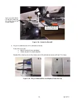
 - Fasten the Standoff

Insert screw 34-01336-16 

and washer 34-60095-46 

thru existing hole into the 

harness standoff.

Standoff supplied with 

harness 22-03090-00

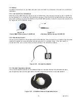
4. Plug in the antenna wires to the eSolutions module.

Follow the color code:

Blue connector to 

b

lue receptacle

Violet connector to violet receptacle

Reinstall the protective cap on the antenna end of the eSolutions module with two T10 screws. 

Figure 1.2

5

 - Plug in Antenna Wires and Replace Protective Cap


16

62-12110

Summary of Contents for eSolutions Supra 550

Page 1: ...Trailer Rail Refrigeration TM eSolutions Telematics Option Supra 60 Series Units Installation and Commissioning Manual 62 12110 Rev A ...

Page 2: ......

Page 3: ... Carrier Corporation 2020 Printed in U S A February 2020 TM eSolutions Telematics Option Supra 60 Series Units Installation and Commissioning Manual ...

Page 4: ...Manual Revision History 62 12110 Rev Date Reason for Release 01 22 2020 Initial Release A 02 13 2020 Add specific connector and pin location for 950MT pages 5 6 7 ...

Page 5: ... 2 Tools 1 1 3 Schematics 2 1 4 Installation 3 1 5 Options 17 2 Field Commission the eSolutions Module 18 2 1 Commissioning Cable 18 2 2 Configuration Setup on a Laptop 18 2 3 Commissioning the Unit 20 2 4 Decommission a Unit 28 3 Wire Harness Connector Pinout 29 ...

Page 6: ......

Page 7: ...8 08689 01 eSolutions Module Bracket 950 960 units only 1 12 00844 00 Antenna Bracket 4 34 60068 25 M6 Captive Head Screw 25mm 2 34 60324 30 M6 Round Head Screw with Thread Lock Compound 4 34 00944 05 M5 Flat Washer 4 34 01184 05 M5 Nylock Lock Nuts 1 22 03130 00 eSolutions Harness 10 58 00079 02 Wire Tie 10 58 05100 00 Sta Strap 8 4 34 06051 104 Rivnut M6 10 58 00701 07 1 4 Button Plug 1 22 03090...

Page 8: ...be as the indication of good seals Splitting of heat shrink tubing due to over temperature or over shrinking is not allowable Charring of the heat shrink tubing is also not allowable Heat shrink tubing shall not be used in areas where there is vibration as it results in some loss of flexibility of the harness 1 3 Schematics The eSolutions wiring schematic and installation diagrams can be found in ...

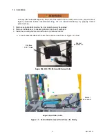
Page 9: ...attery cable lock out standby power if equipped 2 Remove roadside skin condenser grille and top cover if equipped 3 Install the mounting bracket and eSolutions module as follows a Place bracket 68 08632 00 under the control box as shown in Figure 1 3 below Supra 950 and 960 Units Figure 1 3 Control Box Removed from Frame for Clarity Drill three 0 397 holes Supra 550 650 750 850 and 60 Series Units...

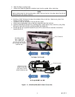
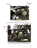
Page 10: ...ee M5 Nylock nuts 34 01184 05 and flat washers 34 00944 05 h Position the 24 pin connector towards the rear of the unit and the two antenna connections towards the front NOTE Before drilling holes for the mounting plate make sure no wires are in the area where the drill will breakthrough to the inside of the box For Supra 5 6 7 8 units le cap Back Front Back Front Figure 1 4 eSolutions Module Ante...

Page 11: ...at constant 12 VDC power 5 Amp fuse holder Pass through grommet SATPWR 1 4 1 Power Harness Installation For Supra 560 660 760 860 950MT and 960 units prior to serial number TFP91605321 install power harness 22 03090 00 as follows Figure 1 6 Remove Pass through and Install Harness b Locate disconnect the 1J plug on the relay board and then locate pin 12 on the connector 950MT uses 3J 12 Remove pass...

Page 12: ...al off the 1J 12 3J 12 on 950MT only wire as near to the terminal as possible Strip the insulation off the wire 0 25 6 62 12110 Supra 950MT only use pin extractor tool 07 00254 00 and remove the 3J 12 pin Figure 1 8 Control Relay Board View 950MT Units only 1J Socket 950MT uses 3J 1J Plug 950MT uses 3J 1J socket pin 12 950MT uses 3J 12 1J plug pin 12 950MT uses 3J 12 ...

Page 13: ...e unit wire 1J 12 3J 12 on 950MT only f Insert the terminal end of the 12 VDC switched power wire into the 1J plug pin 12 position 3J 12 on 950MT only g Plug in the 1J 3J on 950MT only to the relay board Figure 1 9 Terminal Strip Insulation Cut the terminal strip insulation 0 25 ...

Page 14: ... that option is used on the Supra Figure 1 11 Attaching Constant 12 VDC Power Wire NOTE See Tools Stripping Wire Crimping Heat Shrink SP80C 22 03090 00 SP80B F27A ST3 1J Socket 950MT uses 3J Insert wire 1J 12 950MT uses 3J 12 into butt splice on new harness wire labeled SP81B Use proper crimping tool and supplied heat shrink 8 62 12110 New terminal for 1J plug pin 12 position 950MT uses 3J 12 22 0...

Page 15: ...1 11 Attaching Ground Wire from Harness j Attach Ty Wrap 54 00079 02 and secure the harness 22 03090 00 inside the control box Figure 1 12 Ty Wrap Placement NOTE When stacking the ground lugs they should be positioned in a manner that seating interference is avoided Low voltage ground stud Ground 9 62 12110 ...

Page 16: ... 6 7 8 and 950 960 prior to serial number TFP91605321 as follows a Apply dielectric grease 02 00311 02 to the 24 pin connector on the eSolutions harness and plug to the eSolutions module b Plug in 2RP plug on the 22 03130 00 harness to the 1RP plug on the 22 03090 00 harness c Plug in SATPWR plug on the 22 03130 00 harness to SATPWR plug on the 22 03090 00 harness d Plug in SATCOM plug on 22 03130...

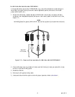
Page 17: ...ber TFP91605321 only connect the eSolutions module harness to the mating unit engine harness connectors and all applicable options fuel sensor door switch power control switch etc Figure 1 15 Power and Communication for 960 Units after S N TFP91605321 Supra 960 Unit Harness 2 Check all harness securing locations to make sure that harness is neatly secured with no loose sections or potential chafin...

Page 18: ...a mounting plate with the notch in sheet metal for 90 degree bend NOTE There are two thicknesses of sheet metal below the Y bracket on top of the unit Move the antenna in 2 from the edge to avoid the two thicknesses 2 12 62 12110 Route antenna cable Route main unit harness as shown Make antenna connections and torque cover screws to 6 in lbs max Route main unit harness as shown Main unit harness f...

Page 19: ...Ty Wrap 58 05100 00 Edge Clip 58 01441 00 3 Secure the remainder of the antenna harness and the eSolutions harness as shown in the series of pictures Figure 1 19 Securing the Antenna 560 660 760 860 Run the antenna wire along engine harness Secure as shown Continue along engine harness Use existing white clamps to secure 13 62 12110 ...

Page 20: ...Figure 1 20 Ty Wrap Locations 760 and 860 Units Figure 1 21 Edge Clip Placement 760 and 860 Units Edge clip 58 01428 00 Run the antenna wire along engine harness Secure as shown 14 62 12110 ...

Page 21: ... 60324 30 x2 Captive Head with threadlock Route antenna harness along existing harness and secure with ty wraps every 6 to 8 Figure 1 23 Routing and Securing the Antenna Harness 950 and 960 units Antenna harness routing 15 62 12110 12 00844 00 4G Antenna ...

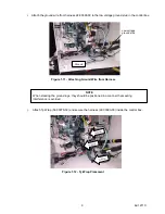
Page 22: ...ied with harness 22 03090 00 4 Plug in the antenna wires to the eSolutions module Follow the color code Blue connector to blue receptacle Violet connector to violet receptacle Reinstall the protective cap on the antenna end of the eSolutions module with two T10 screws Figure 1 25 Plug in Antenna Wires and Replace Protective Cap 16 62 12110 ...

Page 23: ... follow instructions in the field install kit Figure 1 29 eSolutions Remote Temperature Sensor 1 5 Options Installation instructions are provided with each option kit Refer to schematics in Section 3 for additional information 1 5 1 Fuel Level Sensor eSolutions Either the Carrier OEM Ultrasonic fuel level sensor 12 00675 00 or the eSolutions fuel level sensor 12 00787 50 can be installed if it is ...

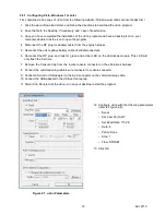
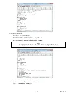
Page 24: ...erTerminal Communications program included with Microsoft Windows 98 2000 and XP which is used to monitor communications between the laptop and the eSolutions module Procedures for configuring laptops running Microsoft Vista Windows 7 or later and Windows 98 2000 and XP are detailed below NOTE Before commissioning the eSolutions system ensure the following Summit software must have DataTrak The pr...

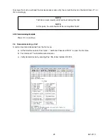
Page 25: ...ve battery cable if still disconnected 6 Reconnect the RP plug and look for green and amber LED on the eSolutions module This LED will only flash the first time 7 Remove the Console Cap from the 4 wire console connector on the eSolutions harness 8 Connect the commissioning cable 4 wire connector to console connector 9 Connect a Serial to USB adapter to the 9 pin connector on the commissioning cabl...

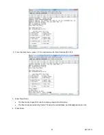
Page 26: ...e name 115200 and save the setup file on your desktop 8 A HyperTerminal session called 115200 has now been setup and can be used in the future to communicate with the eSolutions System 2 3 Commissioning the Unit 1 Open the uCon or HyperTerminal application and press the space bar The eSolutions user menu will open At this point you are connected to the eSolutions module NOTE Communications Port 1 ...

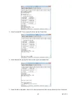
Page 27: ...mission unit Enter Installer ID 0014 3 Enter Fleet Code The fleet code is specific for each company created in eSolutions The fleet code is provided by Carrier Transicold email address esolutions carrier utc com 4 Press Enter 21 62 12110 ...

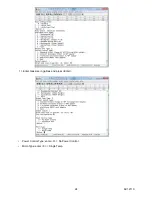
Page 28: ... is usually the trailer number Press Enter 6 Enter the Asset ID usually the trailer number again and press Enter 7 Select Profile Configuration Select 0 unless special instructions are provided by Carrier Transicold 22 62 12110 ...

Page 29: ...l sensor is attached to the eSolutions harness 9 Enter appropriate fuel tank type 10 Install Socket Type 1 Bolts on with the standard 5 bolt flange no adapter or standard NPT thread into tank no adapter Or choose appropriate adapter style NOTE For Supra products choose either 0 or 2 depending on the application 23 62 12110 ...

Page 30: ...11 Enter tank size in gallons and press Enter Power Control Type enter 0 No Power Control Micro Type enter 0 Single Temp 24 62 12110 ...

Page 31: ...itch is attached to the unit engine harness 2 Door switch is attached to the eSolutions harness 13 Configuration Info Verify eSolutions configuration Y To continue commissioning NOTE For Supra products choose either 0 or 2 depending on the application 25 62 12110 ...

Page 32: ...ress C to continue a Verify the Micro is ON The Micro needs to be completely ON Wait until temperatures are displayed b Press C to continue c Text will be displayed in uCon program If communication is established between eS and Summit micro then uCon will display Micro Summit Micro Detected 2 3 2 Test 2 26 62 12110 ...

Page 33: ...open a Press C to continue b Door 1 Polarity 2 of 2 Verify the door is closed c Press C to continue 2 3 4 Test 4 NOTE The door switch can be either normally open or normally closed The commissioning process will configure itself for each sensor 27 62 12110 ...

Page 34: ...oning a Unit A unit can be decommissioned from the Fix menu a At the Start menu enter Command and Enter Password DFIX to open the Fix menu b Fix Command I will initiate decommission c Verify decommission by entering Yes No Enter Installer ID 0014 NOTE Technician must visually verify fuel level during this test NOTE At this point the unit should still be running after Test 2 28 62 12110 ...

Page 35: ...nals None Table 3 3 Console Cap 4 pin CONSOLE CAP 4 pin Component A C CAP C Jumper C C CAP A Jumper Unused Terminals B D Table 3 4 Table 3 5 SATPWR 2 pin SATPWR Terminal Component A DP24 5 Switched PWR Unused Terminals B Table 3 6 SATCOM 3 pin SATCOM Terminal Component A DP24 9 eSolutions RX B DP24 8 eSolutions TX Unused Terminals C Table 3 7 D3 3 pin D3 Terminal Component A SP 2 DP24 3 GND B SP 1...

Page 36: ...3 1 eSolution Wire Harness 30 62 12110 ...

Page 37: ...3 2 eSolution Wire Harness 31 62 12110 ...

Page 38: ...32 62 12110 ...

Page 39: ...ils on warranty coverage www trucktrailer carrier com WARNING Breathing diesel engine exhaust exposes you to chemicals known to the State of California to cause cancer and birth defects or other reproductive harm Always start and operate the engine in a well ventilated area If in an enclosed area vent the exhaust to the outside Do not modify or tamper with the exhaust system Do not idle the engine...

Reviews: