2–3
T-374
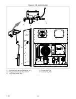
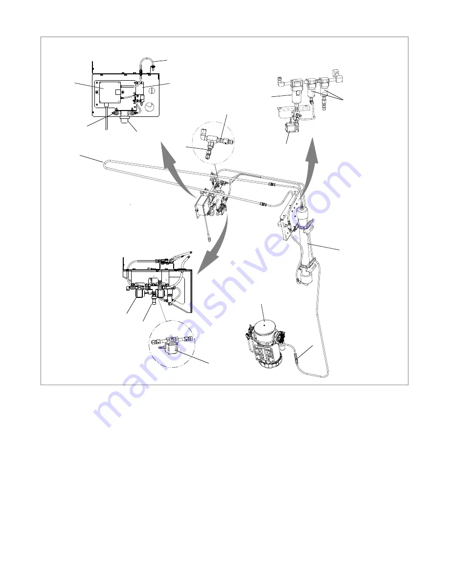
Figure 2.3 EverFRESH Components
1) Air Compressor
2) Check Valve
3) Condensing Loop
4) Water Separator
5) Particulate Filters (2)
6) Water Drain Valve (WDV)
7) Membrane Pressure Transducer (MPT)
8) EverFRESH Air Valve (EA)
9) Nitrogen Membrane Separator
10) Nitrogen Supply Orifice
11) Nitrogen Sampling Orifice
12) EverFRESH Nitrogen Valve (EN)
13) Cargo Air Sensor Inlet
14) Cargo Air Sensor Filter Assembly
15) O
2
Sensor
16) CO
2
Sensor
17) Cargo Air Sensor Outlet
- - - - -
2.3 Optional CO
2
Injection System
There is an optional CO
2
injection kit that can be added to the system that allows CO
2
to be actively injected into
the cargo space during transport. In this configuration, a CO bottle is used with a regulator to maintain an input
pressure of 50 psig, not to exceed 100 psig. There are two CO
2
injection ports: one internal and one external. The
connection is a 1/4” flare fitting with a Schrader valve.
1
Sensor Assembly
Filter Assembly
Summary of Contents for EverFRESH
Page 14: ......
Page 22: ......
Page 30: ......
Page 56: ...T 374 5 26 4 Note the orientation of the check valve 5 Reinstall in reverse order ...
Page 64: ......
Page 66: ......
Page 67: ...8 1 T 374 SECTION 8 SCHEMATICS DIAGRAMS STANDARD UNITS Figure 8 1 Legend Standard Units ...
Page 68: ...T 374 8 2 Figure 8 2 Schematic Standard Units Page 1 ...
Page 69: ...8 3 T 374 Figure 8 3 Schematic Standard Units Page 2 ...
Page 70: ...T 374 8 4 Figure 8 4 Wiring Diagram Standard Units ...
Page 72: ...T 374 9 2 Figure 9 2 Schematic Units with CO2 Injection Page 1 ...
Page 73: ...9 3 T 374 Figure 9 3 Schematic Units with CO2 Injection Page 2 ...
Page 74: ...T 374 9 4 Figure 9 4 Wiring Diagram Units with CO2 Injection ...
Page 99: ......


