3–1
T-374
SECTION 3
OPERATION
3.1 Introduction
This section addresses the operating requirements for the EverFRESH
TM
Controlled Atmosphere option.
Operating parameters are not changed except for EverFRESH settings. For information pertaining to the operation
of the refrigeration system, refer to the Operation and Service Manual for your particular model.
3.2 Operation
The EverFRESH option offers enhanced functionality to help slow the ripening process of perishable cargo by
controlling Carbon Dioxide (CO
2
) and Oxygen (O
2
) levels to specified setpoints. This enables the fresh transport of
perishables on longer voyages. The system controls the container atmosphere with a nitrogen membrane, a fresh
air solenoid and an optional CO
2
injection kit.
During the nitrogen control mode, CO
2
and O
2
are replaced with nitrogen proportionally. EverFRESH also utilizes
the cargo’s natural respiration to control CO
2
and O
2
levels. Additionally, opening and closing a fresh air valve
allows for raising O
2
levels and controlling CO
2
for high respiring cargos. An O
2
sensor monitors O
2
levels and
allows the system to prevent O
2
levels from dropping below the lower setpoint. A CO
2
sensor provides CO
2
levels
to the controller to allow the control algorithm to activate the required EverFRESH components. For low respiring
cargoes requiring high CO
2
setpoints, the CO
2
injection system can be used to maintain CO
2
levels.
NOTICE
While the EverFRESH option is operating, the process of removing ethylene needs to be
performed with external ethylene scrubbers.
3.3 EverFRESH Air and Gas Flow
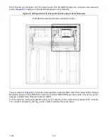
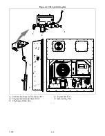
The EverFRESH system (see
) uses an EverFRESH Air Compressor (EAC) mounted to the front of the
refrigeration unit to increase the pressure of the air inside the system. The higher-pressure air will exit the
compressor and go through a check valve that prevents moisture and debris from migrating back to the
compressor in the off cycle. The warm, moisture laden air is brought inside the refrigerated space and passed
through a condensing loop, consisting of a single piece of copper tubing located above the fan deck. As the
compressed air is exposed to the cooler temperature of the cargo space, moisture will condense and be carried out
to the filter assembly.
The filter assembly consists of a water separator and two particulate filters. Any of the condensed moisture will be
removed at the water separator. Immediately after the water separator is the first of two particulate filters, to
remove additional moisture and debris. The condensate and any solid material will settle to the bottom of the filter
assembly and be blown out of the line when the Water Drain Valve (WDV) opens. The water will drip onto the
evaporator coil and down the defrost drain line. The WDV will energize during the initial unit startup when the air
compressor starts. It will also open periodically during air compressor operation to remove accumulated
condensate and again before the air compressor is disengaged.
The compressed air then passes through the second particulate filter. This filter drains any remaining moisture
from the system through the EverFRESH Air Valve (EA) solenoid. This will open after the WDV operates for
draining moisture and when fresh air is required in the system. The EA maintains the desired oxygen levels inside
the cargo space. When the controller detects that oxygen levels are dropping below the threshold setting, it will
open the EA valve to force the clean, dry, pressurized, air into the cargo space. Since this air contains 21%
oxygen, it will increase the concentration of oxygen available for respiration. Just before the EA is the Membrane
Pressure Transducer (MPT) where the controller will monitor system pressure and can determine if the Nitrogen
Membrane Separator is maintaining good flow. When the EA is closed, the clean, dry air will exit the particulate
filter and enter the bottom of the Nitrogen Membrane Separator. Inside the separator, the air will enter thousands of
tiny hollow fibers. The smaller, faster molecules of oxygen and carbon dioxide will pass through the walls of the
membrane fibers, exit the separator through a port on the side, and then are exhausted out the front of the
refrigeration unit to the atmosphere. The larger, slower nitrogen molecules stay trapped in the fibers until they exit
the top of the separator.
As the nitrogen leaves the separator, it is piped above the fan deck to the nitrogen orifices. The orifices provide a
restriction that helps control the gas flow. The nitrogen supply orifice will regulate the flow of nitrogen out to the air
stream where the evaporator fans will blow it across the evaporator and down into the t-slots where it will enter the
Summary of Contents for EverFRESH
Page 14: ......
Page 22: ......
Page 30: ......
Page 56: ...T 374 5 26 4 Note the orientation of the check valve 5 Reinstall in reverse order ...
Page 64: ......
Page 66: ......
Page 67: ...8 1 T 374 SECTION 8 SCHEMATICS DIAGRAMS STANDARD UNITS Figure 8 1 Legend Standard Units ...
Page 68: ...T 374 8 2 Figure 8 2 Schematic Standard Units Page 1 ...
Page 69: ...8 3 T 374 Figure 8 3 Schematic Standard Units Page 2 ...
Page 70: ...T 374 8 4 Figure 8 4 Wiring Diagram Standard Units ...
Page 72: ...T 374 9 2 Figure 9 2 Schematic Units with CO2 Injection Page 1 ...
Page 73: ...9 3 T 374 Figure 9 3 Schematic Units with CO2 Injection Page 2 ...
Page 74: ...T 374 9 4 Figure 9 4 Wiring Diagram Units with CO2 Injection ...
Page 99: ......


