T-374
3–2
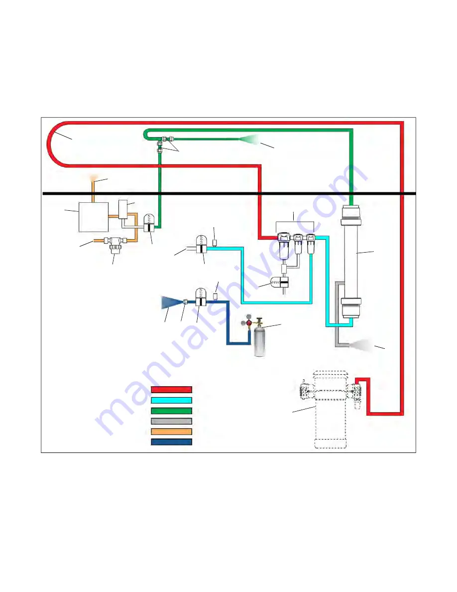
cargo space. The nitrogen sampling orifice regulates the flow of nitrogen to the EverFRESH Nitrogen Valve (EN).
The controller will open EN to allow the gas to flow into the sensor package for testing at the O
2
sensor. Elevated
amounts of oxygen indicate the nitrogen membrane may be clogged. EN is only energized during Pre-trip test P20-
5 N2 Check. Otherwise, when EN is closed during normal operation, gas is forced out of the nitrogen supply orifice.
After having the oxygen level tested, the nitrogen will flow through the CO
2
sensor and then is exhausted back into
the cargo air stream above the fan deck.
On systems equipped with a CO
2
Injection option, the CO
2
Injection Valve (CSV) will control to the CO
2
setpoint.
As CO
2
levels drop below the setpoint, the CSV will open to raise CO
2
levels.
Figure 3.1 EverFRESH Air and Gas Flow Diagram
1) Air Compressor
2) Condensing Loop
3) Water Separator & Particulate Filters
4) Water Drain Valve (WDV)
5) Membrane Pressure Transducer (MPT)
6) EverFRESH Air Valve (EA)
7) Fresh Air Supply to Cargo Space
8) Nitrogen Membrane
9) O
2
and CO
2
Sent to Ambient
10) Nitrogen Supply to Cargo Space
11) Nitrogen Orifices (supply and sampling)
12) EverFRESH Nitrogen Valve (EN)
13) O
2
Sensor
14) CO
2
Sensor
15) Sensor Filter Assembly
16) Cargo Air Sensor Inlet
17) Cargo Air Sensor Outlet
18) CO
2
Injection Bottle (not included with equipment)
19) CO
2
Injection Pressure Transducer (IPT)
20) CO
2
Injection Valve (CSV) - Option
21) CO
2
Supply Orifice Cap
22) CO
2
Supply to Cargo Space - Option
- - - - -
Compressed Ambient Air
Clean Dry Air
Nitrogen
Oxygen & Carbon Dioxide
Cargo Air
Carbon Dioxide
Fan Deck
Summary of Contents for EverFRESH
Page 14: ......
Page 22: ......
Page 30: ......
Page 56: ...T 374 5 26 4 Note the orientation of the check valve 5 Reinstall in reverse order ...
Page 64: ......
Page 66: ......
Page 67: ...8 1 T 374 SECTION 8 SCHEMATICS DIAGRAMS STANDARD UNITS Figure 8 1 Legend Standard Units ...
Page 68: ...T 374 8 2 Figure 8 2 Schematic Standard Units Page 1 ...
Page 69: ...8 3 T 374 Figure 8 3 Schematic Standard Units Page 2 ...
Page 70: ...T 374 8 4 Figure 8 4 Wiring Diagram Standard Units ...
Page 72: ...T 374 9 2 Figure 9 2 Schematic Units with CO2 Injection Page 1 ...
Page 73: ...9 3 T 374 Figure 9 3 Schematic Units with CO2 Injection Page 2 ...
Page 74: ...T 374 9 4 Figure 9 4 Wiring Diagram Units with CO2 Injection ...
Page 99: ......


