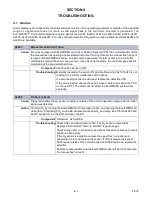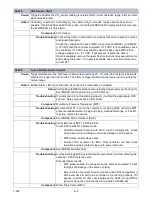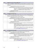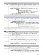
5–7
T-374
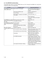
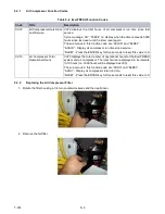
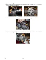
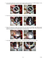
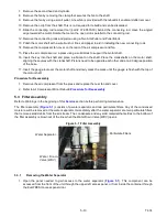
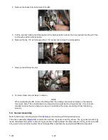
4. Remove crossbars from the air compressor using a 3/4” wrench.
5. Remove the cylinder from the air compressor by removing the 2 - 3/16” hex bolts and pulling off the piston.
Use caution not to damage the fan. Discard bolts, do not reuse.
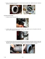
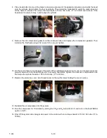
6. Remove the piston guide and rings from the piston.
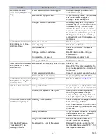
7. Inspect the piston and cylinder walls for signs of damage, etching in either component.
• If damage is minor, lightly honing the cylinder is acceptable.
• If cylinder walls or piston are damaged, perform a major rebuild (kit #18-10185-21).
8. Remove the second head and cylinder, inspecting for damage following steps 3, 5, 6 and 7. If all
components are satisfactory, complete the minor rebuild by reassembling.
Summary of Contents for EverFRESH
Page 14: ......
Page 22: ......
Page 30: ......
Page 56: ...T 374 5 26 4 Note the orientation of the check valve 5 Reinstall in reverse order ...
Page 64: ......
Page 66: ......
Page 67: ...8 1 T 374 SECTION 8 SCHEMATICS DIAGRAMS STANDARD UNITS Figure 8 1 Legend Standard Units ...
Page 68: ...T 374 8 2 Figure 8 2 Schematic Standard Units Page 1 ...
Page 69: ...8 3 T 374 Figure 8 3 Schematic Standard Units Page 2 ...
Page 70: ...T 374 8 4 Figure 8 4 Wiring Diagram Standard Units ...
Page 72: ...T 374 9 2 Figure 9 2 Schematic Units with CO2 Injection Page 1 ...
Page 73: ...9 3 T 374 Figure 9 3 Schematic Units with CO2 Injection Page 2 ...
Page 74: ...T 374 9 4 Figure 9 4 Wiring Diagram Units with CO2 Injection ...
Page 99: ......

