5–9
T-374
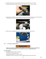
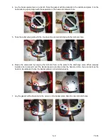
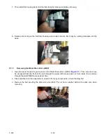
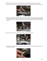
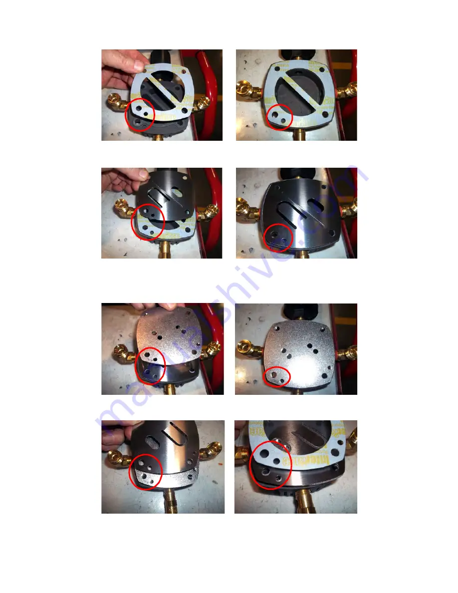
4. Lay the head upside down on a bench. Take the gasket with the material in the middle and place it on the
head lettering up and align with the separation in the head and indicator hole.
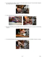
5. Take the outlet valve plate with the line down the center and align with the indicator hole.
6. Reuse the valve plate by aligning the indicator hole on the plate to the discharge valve. When properly
installed, two holes will cover the discharge valve and two holes the head is visible. If you cannot see the
head on two adjacent holes, the backer plate is not installed properly.
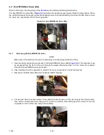
7. Lay the gasket without material in the center on the backer plate. Align the two indicator holes.
Summary of Contents for EverFRESH
Page 14: ......
Page 22: ......
Page 30: ......
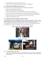
Page 56: ...T 374 5 26 4 Note the orientation of the check valve 5 Reinstall in reverse order ...
Page 64: ......
Page 66: ......
Page 67: ...8 1 T 374 SECTION 8 SCHEMATICS DIAGRAMS STANDARD UNITS Figure 8 1 Legend Standard Units ...
Page 68: ...T 374 8 2 Figure 8 2 Schematic Standard Units Page 1 ...
Page 69: ...8 3 T 374 Figure 8 3 Schematic Standard Units Page 2 ...
Page 70: ...T 374 8 4 Figure 8 4 Wiring Diagram Standard Units ...
Page 72: ...T 374 9 2 Figure 9 2 Schematic Units with CO2 Injection Page 1 ...
Page 73: ...9 3 T 374 Figure 9 3 Schematic Units with CO2 Injection Page 2 ...
Page 74: ...T 374 9 4 Figure 9 4 Wiring Diagram Units with CO2 Injection ...
Page 99: ......


