5–19
T-374
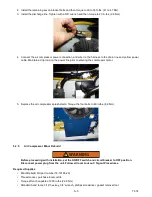
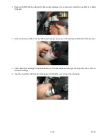
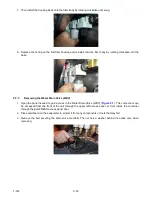
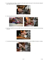
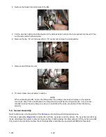
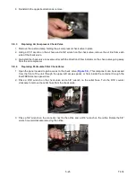
5. Remove the three 1/4” x 20 screws with a 7/16” socket and remove the coil assembly.
6. To install, follow the removal steps in reverse.
NOTE
When reinstalling the EA, remove the fittings from the existing valve body and place on the replace
-
ment valve body. This is best suited to be completed on a work bench using wrenches. It is not recom
-
mended to place the valve body in a vice as it could distort the valve preventing it from functioning
properly.
5.5 EverFRESH Nitrogen Valve (EN)
Refer to Warnings in the beginning of this
section before performing maintenance.
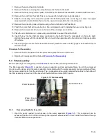
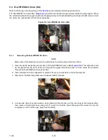
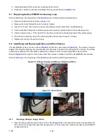
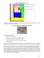
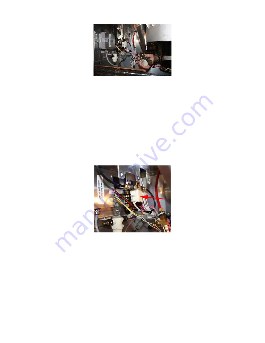
The EverFRESH Nitrogen Valve (EN) (
) opens to allow gas to flow into the sensor package for testing at
the O
2
sensor.
Figure 5.3 EverFRESH Nitrogen Valve (EN)
5.5.1
Removing the EverFRESH Nitrogen Valve
NOTE
Make note of the direction arrow on the valve body to ensure proper direction of flow.
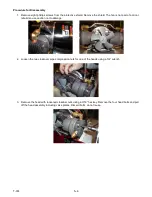
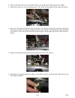
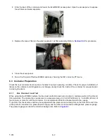
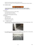
1. Open the panel needed to gain access to the EverFRESH Nitrogen Valve (EN) (
). This
component can be accessed from the front of the unit through the upper left access panel, or from inside the
container through the EverFRESH access panel door.
2. Place cardboard on the evaporator to protect it from any components or tools that may fall.
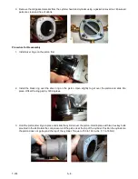
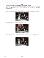
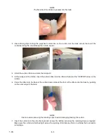
3. When removing from the upper left access panel, remove the EA valve assembly first for easier access. Do
not cut the wires on the EA coil. Removing the evaporator fan motor will allow for more space but not
necessary. When removing from the back of the unit through the EverFRESH access panel, access to the
components is easier.
Summary of Contents for EverFRESH
Page 14: ......
Page 22: ......
Page 30: ......
Page 56: ...T 374 5 26 4 Note the orientation of the check valve 5 Reinstall in reverse order ...
Page 64: ......
Page 66: ......
Page 67: ...8 1 T 374 SECTION 8 SCHEMATICS DIAGRAMS STANDARD UNITS Figure 8 1 Legend Standard Units ...
Page 68: ...T 374 8 2 Figure 8 2 Schematic Standard Units Page 1 ...
Page 69: ...8 3 T 374 Figure 8 3 Schematic Standard Units Page 2 ...
Page 70: ...T 374 8 4 Figure 8 4 Wiring Diagram Standard Units ...
Page 72: ...T 374 9 2 Figure 9 2 Schematic Units with CO2 Injection Page 1 ...
Page 73: ...9 3 T 374 Figure 9 3 Schematic Units with CO2 Injection Page 2 ...
Page 74: ...T 374 9 4 Figure 9 4 Wiring Diagram Units with CO2 Injection ...
Page 99: ......

