5–21
T-374
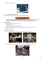
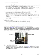
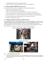
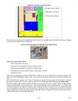
Figure 5.4 Sensor Assembly
5.6.1
Replacing the Sensor Air Filter Element
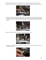
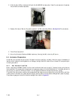
1. Follow container venting procedures before performing any maintenance on the sensor air filter element.
Refer to
2. Open the panel needed to gain access to the sensor air filter element (
). This component can be
accessed from the front of the unit through the upper left access panel, or from inside the container through
the EverFRESH access panel door.
3. Unscrew and remove the filter cup from the bottom of the sensor air filter assembly.
4. Remove the filter element from the filter assembly.
5. Install the sensor air filter element by reversing the above steps. Tighten by hand only.
5.6.2
Removing the O
2
Sensor
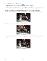
1. Follow container venting procedures before performing any maintenance on the O
2
sensor. Refer to
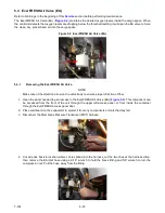
2. Open the panel needed to gain access to the O
2
sensor (
). This component can be accessed
from the front of the unit through the upper left access panel, or from inside the container through the
EverFRESH access panel door.
3. Remove the cushion clamp and screws that secure the O
2
sensor.
4. Cut the wire tie that secures the wiring to the O
2
sensor body.
5. Unplug the wiring connector from the receptacle.
6. Remove the O
2
sensor from the O
2
sensor housing.
7. Install the O
2
sensor by reversing the above steps.
8. Perform an “AutCA” procedure to calibrate the oxygen sensor prior to operation. Refer to
.
5.6.3
Removing the CO
2
Sensor
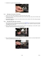
1. Follow container venting procedures before performing any maintenance on the CO
2
sensor. Refer to
2. Open the panel needed to gain access to the CO
2
sensor (
). This component can be accessed
from the front of the unit through the upper left access panel, or from inside the container through the
EverFRESH access panel door.
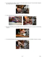
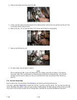
3. Remove the electrical connector and the inlet and outlet tubes from the body of the sensor.
4. Loosen the screws which holds the CO
2
sensor to the fan deck bracket.
CO
2
Sensor
O
2
Sensor
Air Filter
Element
Summary of Contents for EverFRESH
Page 14: ......
Page 22: ......
Page 30: ......
Page 56: ...T 374 5 26 4 Note the orientation of the check valve 5 Reinstall in reverse order ...
Page 64: ......
Page 66: ......
Page 67: ...8 1 T 374 SECTION 8 SCHEMATICS DIAGRAMS STANDARD UNITS Figure 8 1 Legend Standard Units ...
Page 68: ...T 374 8 2 Figure 8 2 Schematic Standard Units Page 1 ...
Page 69: ...8 3 T 374 Figure 8 3 Schematic Standard Units Page 2 ...
Page 70: ...T 374 8 4 Figure 8 4 Wiring Diagram Standard Units ...
Page 72: ...T 374 9 2 Figure 9 2 Schematic Units with CO2 Injection Page 1 ...
Page 73: ...9 3 T 374 Figure 9 3 Schematic Units with CO2 Injection Page 2 ...
Page 74: ...T 374 9 4 Figure 9 4 Wiring Diagram Units with CO2 Injection ...
Page 99: ......


