T-374
5–24
5.8.2
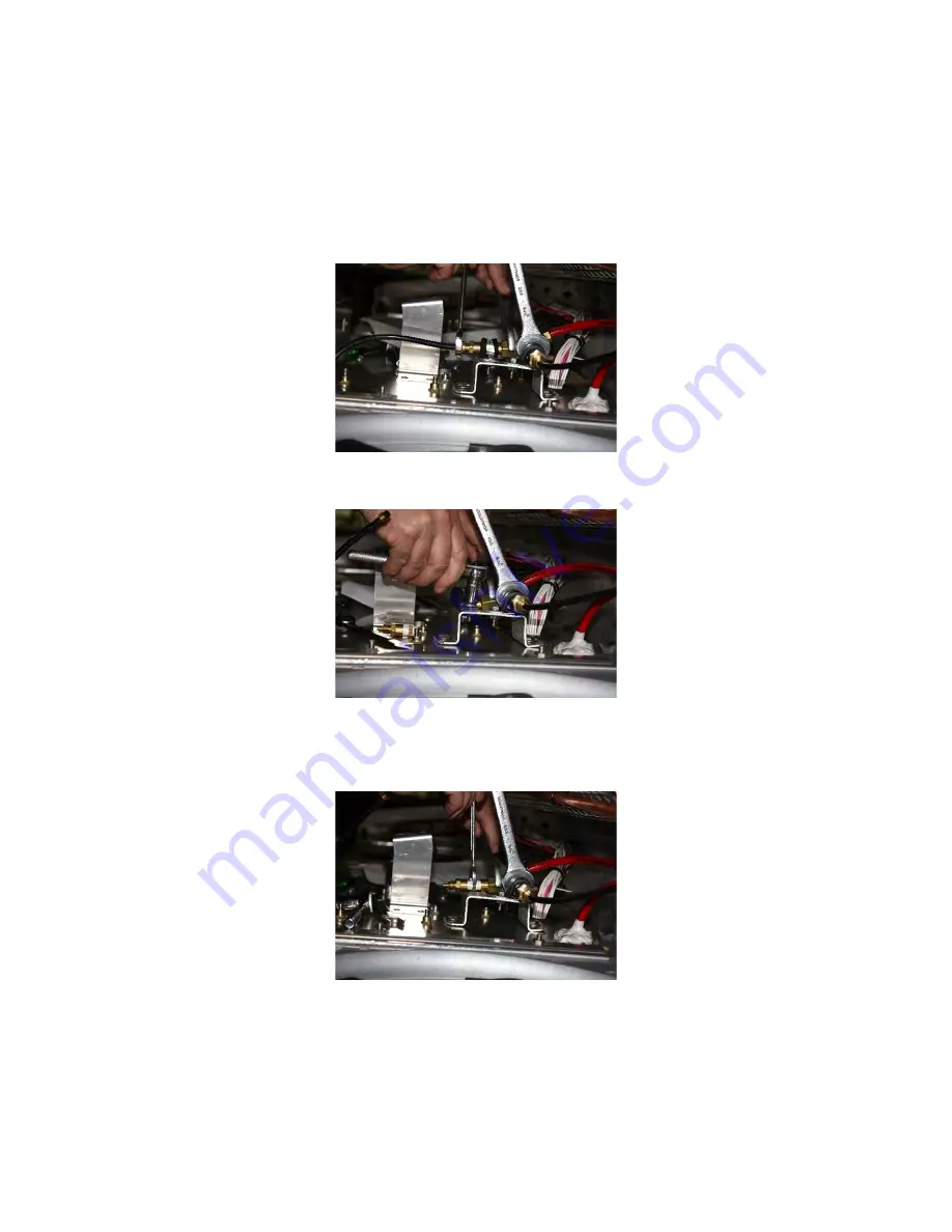
Replacing Nitrogen Sampling Orifices
NOTE
Extra care should be taken to not allow any material to contaminate the orifice.
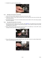
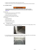
1. Open the panel needed to gain access to the orifice (
). This component can be accessed from the
front of the unit through the upper left access panel, or from inside the container through the EverFRESH
access panel door.
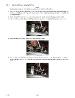
2. Remove rivets from the return air panel and support in an upright position allowing access to orifices.
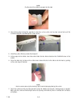
3. Using a 9/16” wrench on the air line fitting and an 3/4” wrench on the adjacent fitting, remove the air line.
4. Remove the cushion clamp holding the sampling orifice in place.
5. Using a 3/4” wrench on the adapter connected to the Tee, remove the 7/16” orifice. Note the orifice is
located opposite of the air line output. Remove the orifice from the air line connector using a 7/16” and 9/16”
wrench.
Summary of Contents for EverFRESH
Page 14: ......
Page 22: ......
Page 30: ......
Page 56: ...T 374 5 26 4 Note the orientation of the check valve 5 Reinstall in reverse order ...
Page 64: ......
Page 66: ......
Page 67: ...8 1 T 374 SECTION 8 SCHEMATICS DIAGRAMS STANDARD UNITS Figure 8 1 Legend Standard Units ...
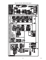
Page 68: ...T 374 8 2 Figure 8 2 Schematic Standard Units Page 1 ...
Page 69: ...8 3 T 374 Figure 8 3 Schematic Standard Units Page 2 ...
Page 70: ...T 374 8 4 Figure 8 4 Wiring Diagram Standard Units ...
Page 72: ...T 374 9 2 Figure 9 2 Schematic Units with CO2 Injection Page 1 ...
Page 73: ...9 3 T 374 Figure 9 3 Schematic Units with CO2 Injection Page 2 ...
Page 74: ...T 374 9 4 Figure 9 4 Wiring Diagram Units with CO2 Injection ...
Page 99: ......

