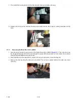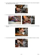
5–25
T-374
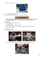
6. Reinstall in the opposite direction as remove.
5.8.3
Replacing Air Compressor Check Valve
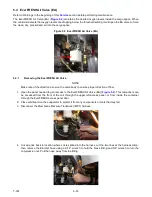
1. Remove the cushion clamp holding the air compressor check valve in place.
2. Using a 9/16” wrench on the air hose and a 5/8” wrench on the check valve, remove the air line from each
side of the check valve.
3. Re-install the check valve in reverse order with the direction of flow indicator on the check valve going away
from the air compressor.
5.8.4
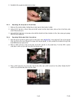
Replacing Particulate Filter Check Valve
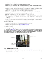
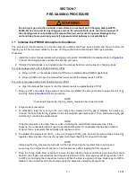
1. Open the panel needed to gain access to the check valve (
). This component can be accessed
from the front of the unit through the upper left access panel, or from inside the container through the
EverFRESH access panel door.
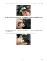
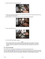
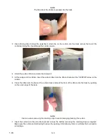
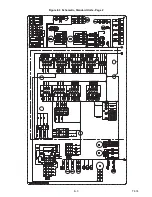
2. Place a 9/16” wrench on the check valve and a 5/8” wrench on the outlet hose. Turn the 9/16” counter
clockwise to remove the outlet hose from the check valve.
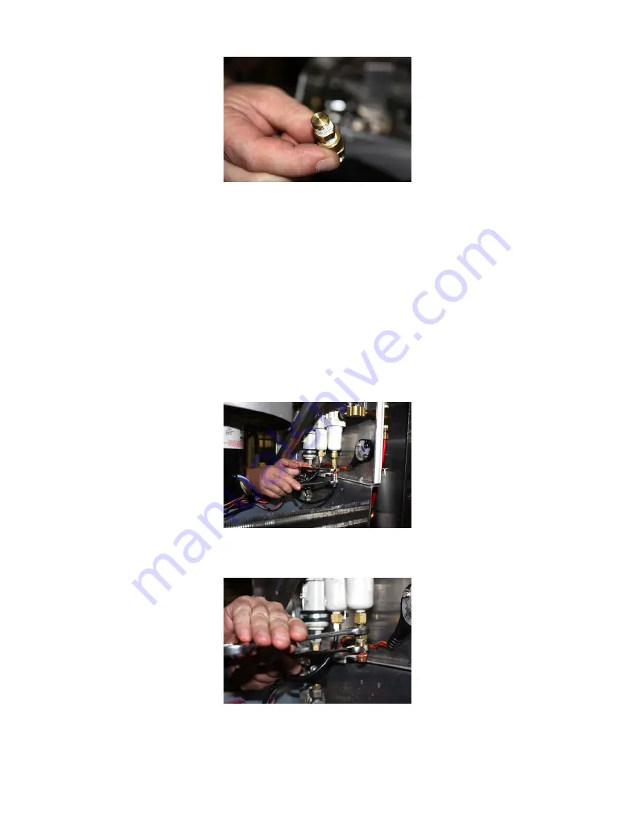
3. Place a 5/8” wrench on the connector next to the orifice and a 9/16” wrench on the orifice. Rotate the 5/8”
wrench counterclockwise removing the orifice.
Summary of Contents for EverFRESH
Page 14: ......
Page 22: ......
Page 30: ......
Page 56: ...T 374 5 26 4 Note the orientation of the check valve 5 Reinstall in reverse order ...
Page 64: ......
Page 66: ......
Page 67: ...8 1 T 374 SECTION 8 SCHEMATICS DIAGRAMS STANDARD UNITS Figure 8 1 Legend Standard Units ...
Page 68: ...T 374 8 2 Figure 8 2 Schematic Standard Units Page 1 ...
Page 69: ...8 3 T 374 Figure 8 3 Schematic Standard Units Page 2 ...
Page 70: ...T 374 8 4 Figure 8 4 Wiring Diagram Standard Units ...
Page 72: ...T 374 9 2 Figure 9 2 Schematic Units with CO2 Injection Page 1 ...
Page 73: ...9 3 T 374 Figure 9 3 Schematic Units with CO2 Injection Page 2 ...
Page 74: ...T 374 9 4 Figure 9 4 Wiring Diagram Units with CO2 Injection ...
Page 99: ......

