6–3
T-374
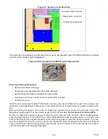
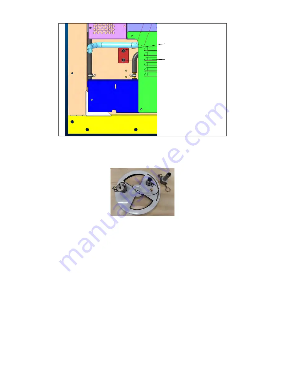
Figure 6.1 Pressure Connection Ports
If the ports are not available, then a Manual Fresh Air panel disc assembly (part # 79-04098-03) with two charging
ports should be installed. Refer to
.
Figure 6.2 Disc Assembly (79-04098-03) with Charging Ports
Prior to performing the leak test:
• Seal the floor drains with plugs.
• Ensure the unit condensate drain line is filled with water.
• Ensure the manual fresh air vent panel is tightly closed.
• Insert plug in drain hose. Install container curtain at the rear door.
• Seal the door shut.
Install the door curtain (part number 76-50036-01) into the curtain track installed in the rear of the container. For
. Always use a new curtain as a small rip in the curtain can result in a failure of the
test.
After connecting the gauges, turn on the air supply and regulate the air pressure to 40-60 psi. When the
Magnehelic gauge reads 2.5 inches of water gauge, shut off the air supply.
Do not exceed 3.5 inches of WG
.
Monitor the Magnehelic pressure gauge for the drop in air pressure in the container. When the Magnehelic
pressure gauge reads 2 inches, start a timer. When the Magnehelic pressure gauge reads 1 inch of WG, stop
timing. The amount of time expired should be no less than four minutes or more for a 40 foot container. If it is less
than the required time, then the container needs to be checked for leaks. Re-pressurize the box to 2.5” WG and
spray potential leak areas with soapy water and seal leaks. Note the typical external and internal leak areas to
check as described in the following paragraphs.
Schrader Valve Locations
Magnahelic connection
Portable air compressor
Summary of Contents for EverFRESH
Page 14: ......
Page 22: ......
Page 30: ......
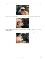
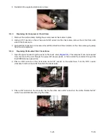
Page 56: ...T 374 5 26 4 Note the orientation of the check valve 5 Reinstall in reverse order ...
Page 64: ......
Page 66: ......
Page 67: ...8 1 T 374 SECTION 8 SCHEMATICS DIAGRAMS STANDARD UNITS Figure 8 1 Legend Standard Units ...
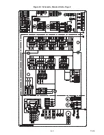
Page 68: ...T 374 8 2 Figure 8 2 Schematic Standard Units Page 1 ...
Page 69: ...8 3 T 374 Figure 8 3 Schematic Standard Units Page 2 ...
Page 70: ...T 374 8 4 Figure 8 4 Wiring Diagram Standard Units ...
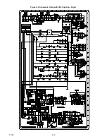
Page 72: ...T 374 9 2 Figure 9 2 Schematic Units with CO2 Injection Page 1 ...
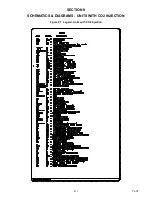
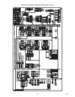
Page 73: ...9 3 T 374 Figure 9 3 Schematic Units with CO2 Injection Page 2 ...
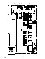
Page 74: ...T 374 9 4 Figure 9 4 Wiring Diagram Units with CO2 Injection ...
Page 99: ......

