T-374
6–4
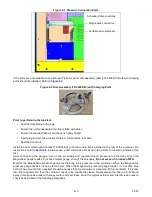
Figure 6.3 Magnehelic Gauge (Kit # 07-00177-20)
External Checks:
Check for leaks with the following recommended checks. Re-pressurize the container to 2 inches water gauge and
look for leaks at the following areas using soapy water (mixture of dish detergent and water) looking for bubbles.
• Inspect the evaporator unit access panels. Check that gasket is properly in place. Tighten the access panel
bolts to 60 inch-lbs. and caulk if necessary.
• Inspect at the defrost drain outlet line. If leaking, complete other checks and re-inspect internally.
• Inspect the unit / container box joints. Caulk if necessary.
• Inspect the through-wire bulkhead connections. Secure and caulk if required.
• Inspect the container floor drains under the container (if accessible). If leaking, complete external checks
and reinspect internally.
• Inspect the rear door seals. Ensure curtain is properly installed (curtain should be visible throughout the
perimeter of the doors if installed without a curtain track). Remove and install new curtain. De-pressurize the
container prior to opening the container.
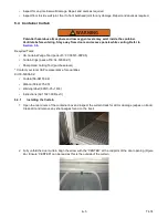
• Ensure Manual Fresh Air Panel is equipped with collars (Part # 79-04064-00).
Figure 6.4 Fresh Air Panel Collars
Internal Checks:
Remove pressure within the container and perform the inspections listed below. On completion of the checks and
any associated repairs, it is recommended to test the unit again to verify it now meets the required level.
• Inspect the curtain for any rips. Replace curtain.
• Inspect the container floor drains. Ensure they are properly sealed. Standard drains can not be used.
• Inspect the defrost drain outlet line. Confirm drain line is filled with water.
Start Timer*
Shut Off Air Supply
Check Container for
Leaks
* 40’ Container - at least 4 minutes
Collars
Fresh Air Panel
Summary of Contents for EverFRESH
Page 14: ......
Page 22: ......
Page 30: ......
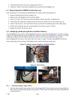
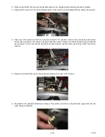
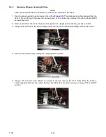
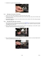
Page 56: ...T 374 5 26 4 Note the orientation of the check valve 5 Reinstall in reverse order ...
Page 64: ......
Page 66: ......
Page 67: ...8 1 T 374 SECTION 8 SCHEMATICS DIAGRAMS STANDARD UNITS Figure 8 1 Legend Standard Units ...
Page 68: ...T 374 8 2 Figure 8 2 Schematic Standard Units Page 1 ...
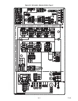
Page 69: ...8 3 T 374 Figure 8 3 Schematic Standard Units Page 2 ...
Page 70: ...T 374 8 4 Figure 8 4 Wiring Diagram Standard Units ...
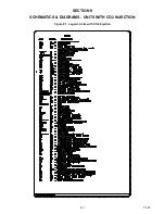
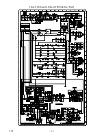
Page 72: ...T 374 9 2 Figure 9 2 Schematic Units with CO2 Injection Page 1 ...
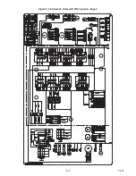
Page 73: ...9 3 T 374 Figure 9 3 Schematic Units with CO2 Injection Page 2 ...
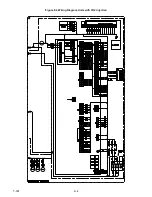
Page 74: ...T 374 9 4 Figure 9 4 Wiring Diagram Units with CO2 Injection ...
Page 99: ......

