7–1
T-374
SECTION 7
PRE-GASSING PROCEDURE
WARNING
!
Do not inject gas into the container unless there is an exhaust port. Charging disk (part# 79-
04098-03) has one port for injecting gas and one for exhaust. Both ports need to be opened. If
the charging disk is not available, the manual fresh air vent must be opened. Damage to the
unit and risk of personal injury exists if a pressure relief pathway is not established.
7.1 Initialize EverFRESH Atmospheric Conditions
The purpose of this procedure is to create optimal conditions that have been studied and shown to slow the
ripening cycle of some commodities by the use of nitrogen (N
2
) and carbon dioxide (CO
2
) gas cylinders.
Procedure:
1. Install the Carrier Transicold disk with charging ports (part # 79-04098-03) if available. Refer to
Connect the charging hose and leave the second port open.
2. If Carrier Transicold disk is not installed, open the manual fresh air vent to allow for charging of gas.
For units equipped with a Vent Position Sensor (VPS):
a. Bring up Cd71 on the display and set to Off mode to disable all EverFRESH operations.
b. Bring up Cd45 and open the manual fresh air vent until the display reads 10 CFM.
For units not equipped with a Vent Position Sensor (VPS):
a. Open the manual fresh air vent until the indicator points to approximately 9 CFM.
3. Bring up Cd71 and enable Purge mode. This is done to establish the amount of time to purge the unit of O
2
and CO
2
. Refer to
for procedure.
NOTE
If not using Purge mode, the CO
2
and O
2
levels can be viewed in Cd44.
4. Purge mode is now active.
5. To establish a lower level of O
2
in the unit, charge the container with N
2
gas to displace the excess O
2
.
Connect the hose from the N
2
regulator to the unit equipped gas injection port. Then, start releasing N
2
gas
until the O
2
% reaches the desired level.
NOTE
If injection pressure is too high, there is a risk of clearing the unit defrost condensate trap. If this
happens, the condensate trap will need to be refilled with water. If condensate trap has been cleared
of water, then a leak exists that will hinder atmosphere control.
6. To establish the proper level of CO
2
in the unit, charge with CO
2
gas. Connect the purging hose to the CO
2
regulator. After injection, the sensor may read much lower than this for at least 30 minutes.
NOTE
Increasing the CO
2
pressure too high will run the risk of freezing the regulator. Due to mixing and
sensor lag, the CO
2
level will continue to rise for some time after stopping the CO
2
regulator.
7. Once the Purge mode timer is expired, remove the gas injection hose connections and close the manual
fresh air vent. If gas concentrations reach desired levels prior to the timer expiring, set Purge mode in Cd71
to OFF prior to closing the manual fresh air vent. When the timer is expired or Purge mode is set to OFF to
disable it, the unit will revert to Fresh mode using the setpoints entered for Purge mode.
Summary of Contents for EverFRESH
Page 14: ......
Page 22: ......
Page 30: ......
Page 56: ...T 374 5 26 4 Note the orientation of the check valve 5 Reinstall in reverse order ...
Page 64: ......
Page 66: ......
Page 67: ...8 1 T 374 SECTION 8 SCHEMATICS DIAGRAMS STANDARD UNITS Figure 8 1 Legend Standard Units ...
Page 68: ...T 374 8 2 Figure 8 2 Schematic Standard Units Page 1 ...
Page 69: ...8 3 T 374 Figure 8 3 Schematic Standard Units Page 2 ...
Page 70: ...T 374 8 4 Figure 8 4 Wiring Diagram Standard Units ...
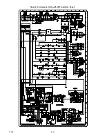
Page 72: ...T 374 9 2 Figure 9 2 Schematic Units with CO2 Injection Page 1 ...
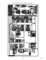
Page 73: ...9 3 T 374 Figure 9 3 Schematic Units with CO2 Injection Page 2 ...
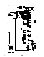
Page 74: ...T 374 9 4 Figure 9 4 Wiring Diagram Units with CO2 Injection ...
Page 99: ......


