3–7
T-374
3.5.4
Code 44 (Cd44)
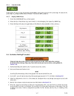
Cd44 allows the user to view the following EverFRESH values: CO
2
setpoint, CO
2
percentage, O
2
setpoint, O
2
percentage, O
2
voltage and Membrane Pressure Transducer (MPT) pressure.
3.5.5
Display Cd44 Values
1. Press the CODE SELECT key on the keypad.
2. Press the Up or Down Arrow keys until “Cd 44” is in the left display, then press the ENTER key.
3. Press the Down Arrow key to toggle between the different values available in this sub menu.
3.6 Container Venting Procedure
WARNING
!
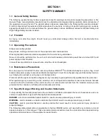
Potential hazardous atmosphere and low oxygen levels may exist inside the container.
Ventilate before entering. Stay away from doors and access panels while venting. (Refer to
1. Set the Start-Stop (ST) switch to the “I” position to turn the unit On.
2. Fully open the manual fresh air vent.
NOTE
Avoid any direct breathing of the venting gases from the manual fresh air vent.
3. Go to Cd71, select Fresh mode and set the operating parameters to 17% O
2
. Refer to
4. Allow the refrigeration unit to run. This allows the evaporator fans to exchange low-oxygen level air with
ambient air.
5. Monitor the container internal environment via Cd44. Refer to
6. When the oxygen level reaches a safe level of approximately 20%, open both of the container rear doors
and pull back the curtain to facilitate the clearing of the hazardous atmosphere. Step away from the
container rear doors. Continue refrigeration operation for five minutes prior to entry or unloading of the
container.
CO
2
Setpoint
CO
2
%
O
2
Setpoint
O
2
%
O
2
Voltage
(displayed in mV)
Membrane Pressure
Transducer (Bar / PSIG)
Summary of Contents for EverFRESH
Page 14: ......
Page 22: ......
Page 30: ......
Page 56: ...T 374 5 26 4 Note the orientation of the check valve 5 Reinstall in reverse order ...
Page 64: ......
Page 66: ......
Page 67: ...8 1 T 374 SECTION 8 SCHEMATICS DIAGRAMS STANDARD UNITS Figure 8 1 Legend Standard Units ...
Page 68: ...T 374 8 2 Figure 8 2 Schematic Standard Units Page 1 ...
Page 69: ...8 3 T 374 Figure 8 3 Schematic Standard Units Page 2 ...
Page 70: ...T 374 8 4 Figure 8 4 Wiring Diagram Standard Units ...
Page 72: ...T 374 9 2 Figure 9 2 Schematic Units with CO2 Injection Page 1 ...
Page 73: ...9 3 T 374 Figure 9 3 Schematic Units with CO2 Injection Page 2 ...
Page 74: ...T 374 9 4 Figure 9 4 Wiring Diagram Units with CO2 Injection ...
Page 99: ......

