T-374
4–6
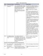
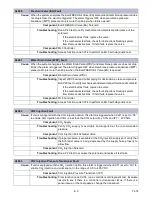
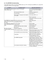
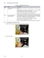
4.2 EverFRESH Troubleshooting
This troubleshooting section is for the EverFRESH option only. Prior to testing the EverFRESH unit, verify that the
refrigeration system is functioning properly.
Condition
Possible Causes
Recommended Actions
EverFRESH Air Compressor
(EAC) Will Not Start
EAC contactor not engaging
Verify that temperature setpoint is in
the correct range for EverFRESH to
operate.
EAC Internal Protector open
Check air compressor IP.
Fuse F3 blown
Check fuse F3.
EAC contactor engaging, but compressor
not running
Check fuses FEF1, 2, 3.
Check input power.
Check motor resistance at the EAC
connector.
EverFRESH Air Compressor
(EAC) Running But Cycling
ON / OFF
EAC shuts off every 45 minutes
Normal duty cycle.
Internal Motor Protector
Check.
EverFRESH Air Compressor
(EAC) Hums But Does Not
Start
Low line voltage
Check voltage.
Single phasing
Check power / fuses.
Shorted or grounded motor windings
Check resistance.
EAC seized
Check current.
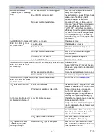
Membrane Pressure
Transducer (MPT) Reading
Low
Dirty EAC intake filter
Replace the intake filter.
Water separator housing / drain leaking
Remove the housing and clean debris.
Verify that the WDV is closing.
Particulate filter housing / drain leaking
Remove the housing and clean debris.
Verify that the WDV is closing.
Leaky valve
Remove the valve and attempt to
remove obstruction. If this is
unsuccessful, replace the valve.
EverFRESH piping leak
Inspect piping for abrasions / cuts in
piping. Verify all connections are tight.
If unable to locate leak, remove the
EAC discharge line and inject 80 psig
of nitrogen or clean dry air into the
system and check for leaks with soapy
water. Ensure the unit locked out when
performing this procedure.
Air compressor defective or leaking
Perform a major / minor rebuild based
on hours of operation.
Summary of Contents for EverFRESH
Page 14: ......
Page 22: ......
Page 30: ......
Page 56: ...T 374 5 26 4 Note the orientation of the check valve 5 Reinstall in reverse order ...
Page 64: ......
Page 66: ......
Page 67: ...8 1 T 374 SECTION 8 SCHEMATICS DIAGRAMS STANDARD UNITS Figure 8 1 Legend Standard Units ...
Page 68: ...T 374 8 2 Figure 8 2 Schematic Standard Units Page 1 ...
Page 69: ...8 3 T 374 Figure 8 3 Schematic Standard Units Page 2 ...
Page 70: ...T 374 8 4 Figure 8 4 Wiring Diagram Standard Units ...
Page 72: ...T 374 9 2 Figure 9 2 Schematic Units with CO2 Injection Page 1 ...
Page 73: ...9 3 T 374 Figure 9 3 Schematic Units with CO2 Injection Page 2 ...
Page 74: ...T 374 9 4 Figure 9 4 Wiring Diagram Units with CO2 Injection ...
Page 99: ......


