5–1
T-374
SECTION 5
SERVICE
WARNING
!
Before servicing unit, make sure the Start-Stop switch (ST) is in the OFF position. Unit circuit
breaker (CB-1) and external power sources are turned OFF and tagged to prevent accidental
energizing of circuits.
WARNING
!
Potential hazardous atmosphere and low oxygen levels may exist inside the container.
Ventilate before entering. Stay away from doors and access panels while venting. (refer to
).
NOTICE
Prior to performing service work, a thorough review and understanding of the entire manual is
recommended.
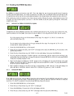
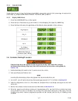
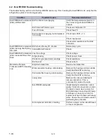
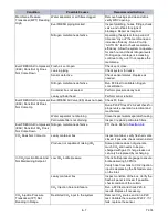
5.1 Maintenance Schedule
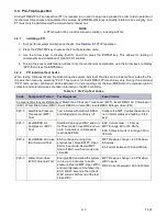
5.2 EverFRESH Air Compressor (EAC) Service
Refer to Warnings in the beginning of this
section before performing maintenance.
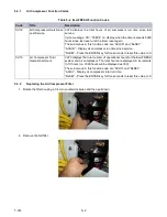
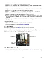
The air compressor (
) is an oil-less, two cylinder compressor mounted on the front of the unit next to the
power cord.
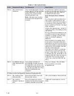
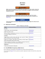
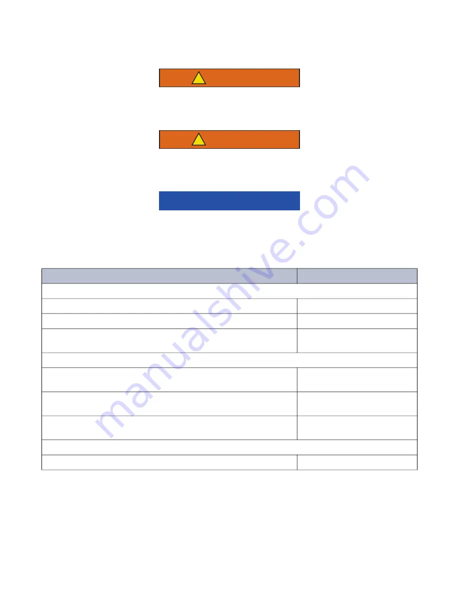
Table 5–1 Maintenance Schedule
Action
Reference Section
Pre-Trip
Verify container meets leak specification.
Replace poly sheet curtain.
Run an “AutCA” to calibrate the O
2
sensor and CO
2
sensor and check
mechanical integrity of components.
Annually
Replace sensor air filter. Inspect and clean water separator. Replace a
sticker with date when making a filter change.
Replace air compressor intake filter and particulate air filters. Replace a
sticker with date when making a filter change.
Check compressor for damage on air compressor coating and repair as
needed. Areas affected should be sanded and repainted.
5000 Hours
Perform minor rebuild of air compressor.
Summary of Contents for EverFRESH
Page 14: ......
Page 22: ......
Page 30: ......
Page 56: ...T 374 5 26 4 Note the orientation of the check valve 5 Reinstall in reverse order ...
Page 64: ......
Page 66: ......
Page 67: ...8 1 T 374 SECTION 8 SCHEMATICS DIAGRAMS STANDARD UNITS Figure 8 1 Legend Standard Units ...
Page 68: ...T 374 8 2 Figure 8 2 Schematic Standard Units Page 1 ...
Page 69: ...8 3 T 374 Figure 8 3 Schematic Standard Units Page 2 ...
Page 70: ...T 374 8 4 Figure 8 4 Wiring Diagram Standard Units ...
Page 72: ...T 374 9 2 Figure 9 2 Schematic Units with CO2 Injection Page 1 ...
Page 73: ...9 3 T 374 Figure 9 3 Schematic Units with CO2 Injection Page 2 ...
Page 74: ...T 374 9 4 Figure 9 4 Wiring Diagram Units with CO2 Injection ...
Page 99: ......

