T-374
5–18
5.4 EverFRESH Air Valve (EA)
Refer to Warnings in the beginning of this
section before performing maintenance.
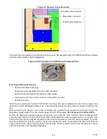
The EverFRESH Air Valve (EA) (
) maintains the desired oxygen levels inside the cargo space. When
the controller detects that oxygen levels are dropping below the threshold setting, it will open the EA valve to force
the clean, dry, pressurized, air into the cargo space.
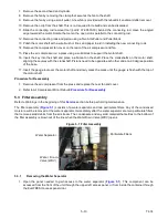
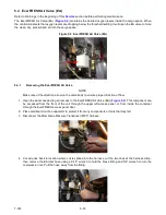
Figure 5.2 EverFRESH Air Valve (EA)
5.4.1
Removing the EverFRESH Air Valve
NOTE
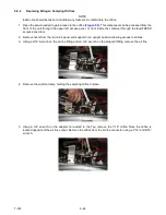
Make note of the direction arrow on the valve body to ensure proper direction of flow.
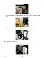
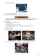
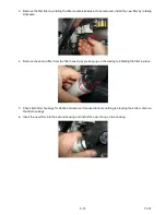
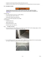
1. Open the panel needed to gain access to the EverFRESH Air Valve (EA) (
). This component can
be accessed from the front of the unit through the upper left access panel, or from inside the container
through the EverFRESH access panel door.
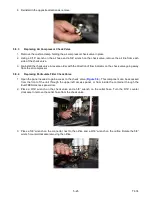
2. Place cardboard on the evaporator to protect it from any components or tools that may fall.
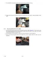
3. Disconnect the Membrane Pressure Transducer (MPT) harness.
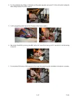
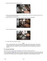
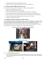
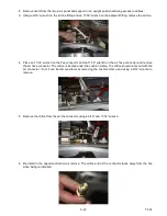
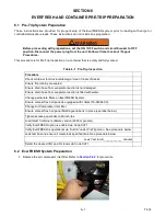
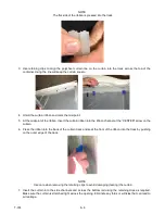
4. Cut wire ties back to location where coil is spliced into the harness, cut the two lines at the harness crimp,
then remove the EA inlet hose using a 9/16” wrench to hold the brass fitting and 5/8” wrench to turn the
compression nut. Pull the hose away from the fitting.
Summary of Contents for EverFRESH
Page 14: ......
Page 22: ......
Page 30: ......
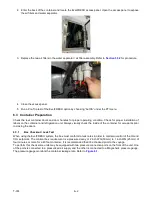
Page 56: ...T 374 5 26 4 Note the orientation of the check valve 5 Reinstall in reverse order ...
Page 64: ......
Page 66: ......
Page 67: ...8 1 T 374 SECTION 8 SCHEMATICS DIAGRAMS STANDARD UNITS Figure 8 1 Legend Standard Units ...
Page 68: ...T 374 8 2 Figure 8 2 Schematic Standard Units Page 1 ...
Page 69: ...8 3 T 374 Figure 8 3 Schematic Standard Units Page 2 ...
Page 70: ...T 374 8 4 Figure 8 4 Wiring Diagram Standard Units ...
Page 72: ...T 374 9 2 Figure 9 2 Schematic Units with CO2 Injection Page 1 ...
Page 73: ...9 3 T 374 Figure 9 3 Schematic Units with CO2 Injection Page 2 ...
Page 74: ...T 374 9 4 Figure 9 4 Wiring Diagram Units with CO2 Injection ...
Page 99: ......

