T-374
5–22
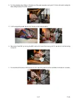
5. Install replacement CO
2
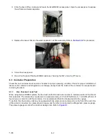
sensor by reversing steps 2 and 3.
6. Perform an “AutCA” procedure to calibrate the CO
2
sensor. Refer to
5.7 Replacing the EverFRESH Condensing Loop
Refer to Warnings in the beginning of this
section before performing maintenance.
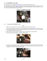
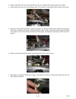
1. Remove the back panel from the container unit.
2. Remove the rivets holding the return air deck in place.
3. Use a 11/16” and 13/16” wrench to remove the fittings on both ends of the condensing loop.
4. Cut the wire ties holding the condensing loop to the return air grill and remove the condensing loop.
5. Install in reverse: Use a 11/16” and 13/16” wrench to connect the condensing loop to the system piping.
6. Wire tie the condensing loop to the return air grille. Place a wire tie every 10 inches.
7. Replace the rivets in the return air deck.
5.8 Identifying and Replacing Orifices and Check Valves
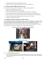
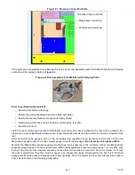
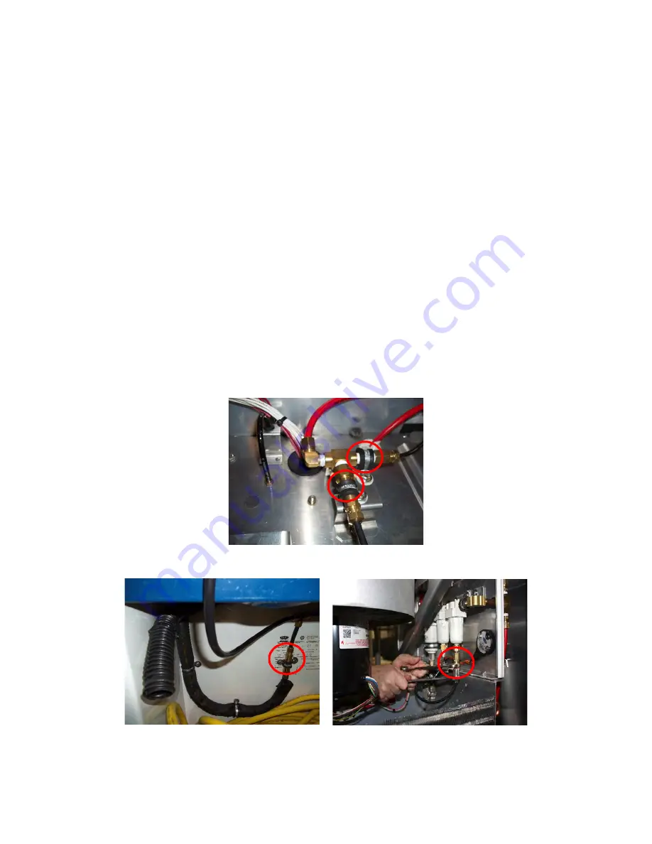
The EverFRESH system has two orifices (
) and two check valves (
). The orifices, nitrogen
supply and nitrogen sampling, are located above the fan deck in between the evaporator fan motors. The check
valves are located near the compressor outside the container and on the particulate filter housing outlet.
Refer to
for location of the orifices and check valves in relation to all of the EverFRESH components.
Refer to Warnings in the beginning of this
section before performing maintenance.
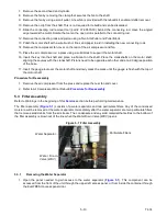
Figure 5.5 Nitrogen Supply and Nitrogen Sampling Orifices
Figure 5.6 Check Valves
5.8.1
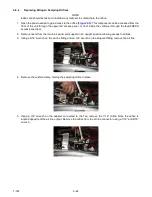
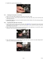
Replacing Nitrogen Supply Orifice
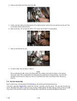
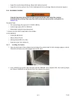
1. Open the panel needed to gain access to the orifice (
). This component can be accessed from the
front of the unit through the upper left access panel, or from inside the container through the EverFRESH
access panel door.
Summary of Contents for EverFRESH
Page 14: ......
Page 22: ......
Page 30: ......
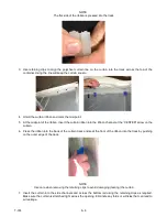
Page 56: ...T 374 5 26 4 Note the orientation of the check valve 5 Reinstall in reverse order ...
Page 64: ......
Page 66: ......
Page 67: ...8 1 T 374 SECTION 8 SCHEMATICS DIAGRAMS STANDARD UNITS Figure 8 1 Legend Standard Units ...
Page 68: ...T 374 8 2 Figure 8 2 Schematic Standard Units Page 1 ...
Page 69: ...8 3 T 374 Figure 8 3 Schematic Standard Units Page 2 ...
Page 70: ...T 374 8 4 Figure 8 4 Wiring Diagram Standard Units ...
Page 72: ...T 374 9 2 Figure 9 2 Schematic Units with CO2 Injection Page 1 ...
Page 73: ...9 3 T 374 Figure 9 3 Schematic Units with CO2 Injection Page 2 ...
Page 74: ...T 374 9 4 Figure 9 4 Wiring Diagram Units with CO2 Injection ...
Page 99: ......

