6–1
T-374
SECTION 6
EVERFRESH AND CONTAINER PRE-TRIP PREPARATION
6.1 Pre-Trip System Preparation
These instructions are provided for proper setup of the EverFRESH system prior to loading with cargo for
controlled atmosphere loads. These instructions do not include box preparation.
WARNING
!
Before proceeding with preparations, set the ON / OFF switch and circuit breaker to OFF
position. Disconnect the power plug from the unit. Follow all local Lockout / Tagout
Procedures.
This procedure is for Pre-Trip Inspection on a container that is empty and fully vented.
6.2 EverFRESH System Preparation
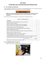
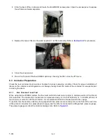
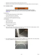
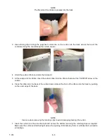
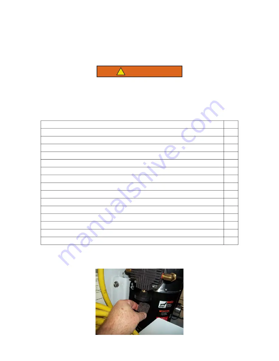
1. Replace the air compressor inlet filter. Refer to
Table 6–1 Pre-Trip Inspection
Procedure
Check container for structural damage / clean T-bars of debris.
Ensure floor drains are sealed.
Ensure drain hose from evaporator section is not damaged.
Ensure drain hose from evaporator section is filled with water.
Change particulate filters on EverFRESH System.
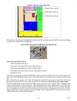
Ensure manual fresh air panel is equipped with collars (79-04064-00).
Change Air Compressor Inlet filter.
Ensure manual fresh air panel Multilingual label is in place (see label below).
Tighten access panel bolts to 60 inch-lbs.
Load latest Container software version (6303 or greater).
Verify EverFRESH option is enabled via Code Cd71.
Verify EverFRESH is operational via “AutCA” under PreTrip menu. See procedure below.
Leak test box and ensure it meets leak specifications. See procedure below.
Leak Test result ____________ minutes
Select the desired CO
2
and O
2
levels via Code Cd71.
Summary of Contents for EverFRESH
Page 14: ......
Page 22: ......
Page 30: ......
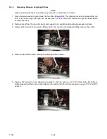
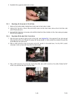
Page 56: ...T 374 5 26 4 Note the orientation of the check valve 5 Reinstall in reverse order ...
Page 64: ......
Page 66: ......
Page 67: ...8 1 T 374 SECTION 8 SCHEMATICS DIAGRAMS STANDARD UNITS Figure 8 1 Legend Standard Units ...
Page 68: ...T 374 8 2 Figure 8 2 Schematic Standard Units Page 1 ...
Page 69: ...8 3 T 374 Figure 8 3 Schematic Standard Units Page 2 ...
Page 70: ...T 374 8 4 Figure 8 4 Wiring Diagram Standard Units ...
Page 72: ...T 374 9 2 Figure 9 2 Schematic Units with CO2 Injection Page 1 ...
Page 73: ...9 3 T 374 Figure 9 3 Schematic Units with CO2 Injection Page 2 ...
Page 74: ...T 374 9 4 Figure 9 4 Wiring Diagram Units with CO2 Injection ...
Page 99: ......

