2–1
T-374
SECTION 2
INTRODUCTION
2.1 Introduction
This manual contains information specific to the Carrier Transicold EverFRESH
TM
Controlled Atmosphere option.
This manual is to be used in conjunction with the separately bound Operation and Service Manual and Service
Parts Manual for the model of your particular refrigeration unit.
The EverFRESH system is able to control container atmosphere by supplying nitrogen and oxygen into the
contained space and simultaneously controlling levels of O
2
and CO
2
. This extends the produce ripening process,
which increases shelf life and enables longer cargo routes for certain perishable commodities. The EverFRESH
system also offers an optional package to actively inject CO
2
into the cargo space during transport.
2.2 Controlled Atmosphere Unit - Component Descriptions
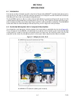
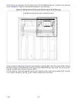
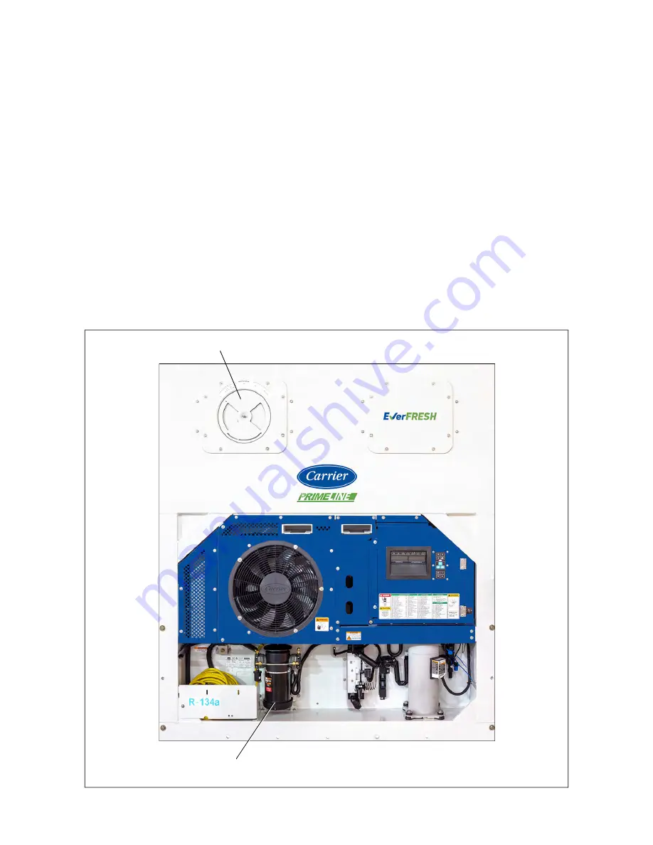
The refrigeration unit is designed so that the majority of its components are accessible from the front (
).
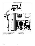
The air compressor for EverFRESH is located below the condenser behind a splash guard. A manually operated
venting system is located in the upper left access panel. The panel may be removed to allow entry into the
evaporator section where the atmosphere sensors, control valves, water separator and air filters are located.
Figure 2.1 Refrigeration Unit - Front
EverFRESH Air Compressor (splash guard removed)
EverFRESH components behind Access Panel
Summary of Contents for EverFRESH
Page 14: ......
Page 22: ......
Page 30: ......
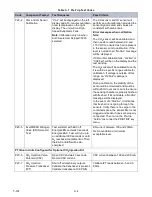
Page 56: ...T 374 5 26 4 Note the orientation of the check valve 5 Reinstall in reverse order ...
Page 64: ......
Page 66: ......
Page 67: ...8 1 T 374 SECTION 8 SCHEMATICS DIAGRAMS STANDARD UNITS Figure 8 1 Legend Standard Units ...
Page 68: ...T 374 8 2 Figure 8 2 Schematic Standard Units Page 1 ...
Page 69: ...8 3 T 374 Figure 8 3 Schematic Standard Units Page 2 ...
Page 70: ...T 374 8 4 Figure 8 4 Wiring Diagram Standard Units ...
Page 72: ...T 374 9 2 Figure 9 2 Schematic Units with CO2 Injection Page 1 ...
Page 73: ...9 3 T 374 Figure 9 3 Schematic Units with CO2 Injection Page 2 ...
Page 74: ...T 374 9 4 Figure 9 4 Wiring Diagram Units with CO2 Injection ...
Page 99: ......


