2-1
62-10848
SECTION 2
Unit Description
2.1
Introduction
Beware of unannounced starting of the unit. The unit
may cycle the fans and operating compressor unex-
pectedly as control requirements dictate. Press the
OFF key on the Cab Command and disconnect the
power plug.
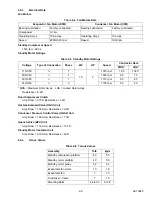
This manual contains Operating Data, Electrical Data
and Service Instructions for the Carrier Transicold
Model 30S truck refrigeration units listed in
Additional support manuals are listed in
The model/serial nameplate is located on the cover.
2.2
General Description
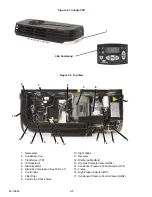
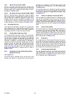
The unit (
) is of the split system type with the
condenser mounted outside the truck body, evaporator
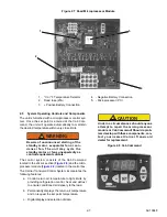
mounted in the body, and a Cab Command control cen-
ter mounted in the driver’s compartment. Two types of
compressor drive are available:
• Road operation: The road compressor is located
in the engine compartment and is driven by the
engine of the vehicle when in operation over-the-
-road
• Road/Standby operation: A second compressor
is mounted in the condensing section and is
driven by an electric motor when in standby
mode.
2.3
Condensing Section
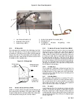
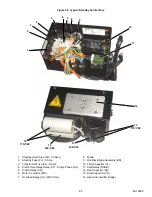
The condensing section (see
) contains the
condenser fan and coil, filter drier, oil separator, hot gas
solenoid valve, receiver, and a condenser pressure
control valve. On road/standby units the condensing
section also houses the standby compressor, control
box and rectifier and houses the transformer assembly
(see
2.3.1
Condenser/Subcooler
The condenser is of the tube and fin type and acts as a
heat exchanger in which the compressed refrigerant
gas is condensed into a liquid and lowered in tempera-
ture. Air movement over the condenser is provided by
a fan mounted in the condensing section.
A portion of the condenser is occupied by the sub-
cooler. Refrigerant leaving the receiver is passed
through the subcooler where additional heat is
removed. Removal of this additional heat helps to
ensure that only liquid refrigerant enters the thermal
expansion valve.
2.3.2
Filter Drier
The drier is a cylindrical shell containing a drying agent
and screen. It is installed in the liquid line and functions
to keep the system clean and remove moisture from
the refrigerant.
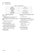
Table 2–1 Model Chart
Model No.
Description
R-134A
Road
Compressor
Standby
Compressor
Condenser
Weight
Evaporator
Weight
8002189
Road Only
4 lb (1.8 kg)
TM 16
---
Road: 88 lb (40 kg)
Road and Standby:
165 lb (75 kg)
66 lb (30 kg)
8002191
Road/Standby
115/1/60Hz
TM 16
8002193
Road/Standby
230/1/60Hz
8002195
Road/Standby
230/3/60Hz
Table 2–2 Additional Support Manuals
Manual Number
Equipment Covered
Type of Manual
62-10835
Integra 30S
Parts List
62-10847
Integra 30S
Easy to Run
62-10849
Integra 30S
Operator’s Manual

