62-10848
5-4
5.3.3
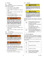
Removing the Manifold Gauge Set
1. While the compressor is still ON, backseat the
high side service valve.
2. Midseat both hand valves on the manifold
gauge set and allow the pressure in the mani-
fold gauge set to be drawn down to low side
pressure. This returns any liquid that may be in
the high side hose to the system.
CAUTION
!
To prevent trapping liquid refrigerant in
the manifold gauge set, be sure set is
brought to suction pressure before dis-
connecting.
3. Backseat the low side service valve. Backseat
both field service couplers and frontseat both
manifold set hand valves. Remove the couplers
from the access valves.
4. Install both service valve stem caps and access
valve caps (finger-tight only).
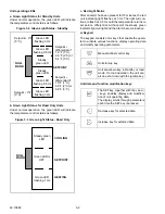
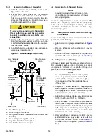
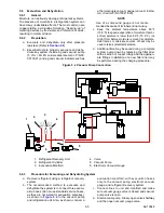
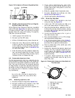
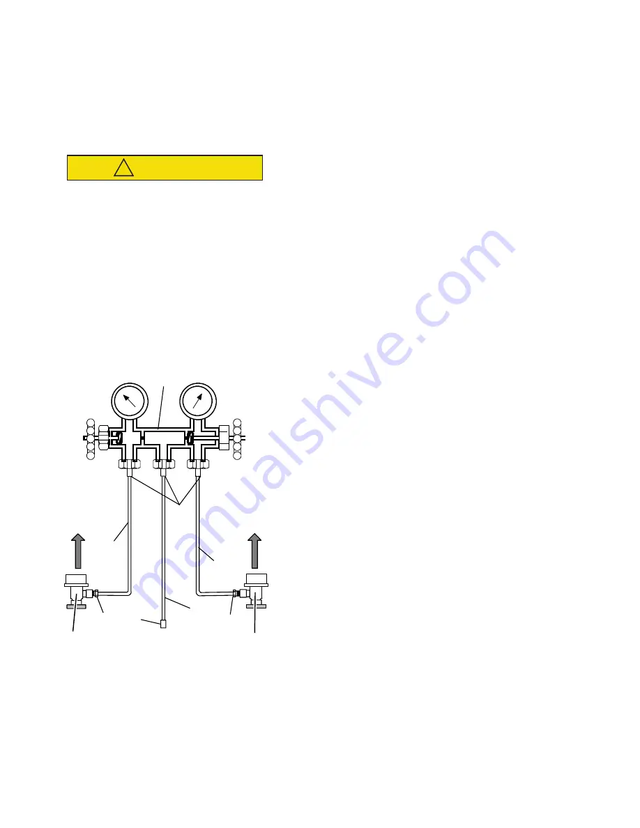
Figure 5.3 Manifold Gauge Set (R-134A)
1. Manifold Gauge Set
2. Hose Fitting (0.5-16 Acme)
3. Refrigeration and/or Evacuation Hose (SAE J2196/
R-134a)
4. Hose Fitting w/O-ring (M14 x 1.5)
5. High Side Field Service Coupler
6. Low Side Field Service Coupler
5.4
Removing the Refrigerant Charge
NOTE
To avoid damage to the earth’s ozone layer,
use a refrigerant recovery system whenever
removing refrigerant.
Connect a refrigerant recovery system (Carrier P/N
MVS-115-F-L-CT (115V) or MVS-240-F-L-CT (240V))
to the unit to remove refrigerant charge. Refer to
instructions provided by the manufacturer of the refrig-
erant recovery system.
5.4.1
Refrigerant Removal From a Non-Working
Compressor
To remove the refrigerant from a compressor that is not
operational, do the following:
a. Attach a manifold gauge set as shown in
b. Recover refrigerant with a refrigerant recovery
system.
c. Service or replace components as required and
leak check the entire system. (See
5.5
Refrigerant Leak Checking
A refrigerant leak check should always be performed
after the system has been opened to replace or repair
a component. To check for leaks in the refrigeration
system, perform the following procedure:
NOTE
Use only R-134A to pressurize the system.
Any other gas or vapor will contaminate the
system which will require additional purging
and evacuation of the high side (discharge)
of the system.
a. If system is without refrigerant, charge system
with refrigerant to build up pressure between 30
to 50 psig (2 to 3.4 Bars). Remove refrigerant
cylinder and leak check all connections.
b. Add sufficient nitrogen to raise system pressure
to 150 to 200 psig (10.21 to 13.61 bar).
c. Check for leaks. The recommended procedure for
finding leaks in a system is with an electronic leak
detector. (Carrier P/N 07-00295-00). Testing joints
with soap suds is satisfactory for locating large
leaks but be necessary when an electronic leak
detector will not function correctly.
d. Remove refrigerant using a refrigerant recovery
system and repair any leaks. Evacuate and
dehydrate the unit. (Refer to
)
Charge unit with refrigerant. (Refer to
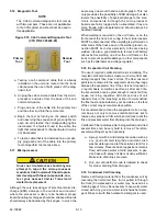
Low Pressure
Gauge
High Pressure
Gauge
Opened
(Backseated)
Hand Valve
Closed
(Frontseated)
Hand Valve
To Low Side
Access Valve
To High Side
Access Valve
BLUE
RED
YELLOW
(Blue Knob)
(Red Knob)


