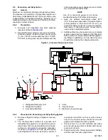
62-10848
5-6
e. Evacuate unit until the electronic vacuum gauge
indicates 2000 microns. Close the electronic
vacuum gauge and vacuum pump valves. Shut
off the vacuum pump. Wait a few minutes to be
sure the vacuum holds.
f. Break the vacuum with clean dry nitrogen. Raise
system pressure to approximately 2 psig (0.14 Bar).
g. Purge nitrogen from system.
h. Repeat steps e through g one time.
i. Evacuate unit to 500 microns. Close off vacuum
pump valve and stop pump. Wait five minutes to
see if vacuum holds. This checks for residual
moisture and/ or leaks.
j. With a vacuum still in the unit, the refrigerant
charge may be drawn into the system from a
refrigerant container on a scale. The correct
amount of refrigerant may be added by observ-
ing the scale. (Refer to
5.7
Charging the Refrigeration System
5.7.1
Checking The Refrigerant Charge
a. Start unit in cooling mode and run for approxi-
mately ten minutes.
b. Partially block off air flow to condenser coil so
discharge pressure rises to 174 psig (12 Bars).
c. The unit is correctly charged when there are no
bubbles in the sight glass.
5.7.2
Installing a Complete Charge
NOTE
It may be necessary to finish charging the
unit using the partial charge method, due to
pressure rise in the high side of the system.
(Refer to
)
a. Dehydrate unit and leave in deep vacuum.
(Refer to
)
b. Place refrigerant cylinder on scale and connect
charging line from cylinder to receiver outlet
(king) valve. Purge charging line at outlet valve.
c. Note weight of refrigerant cylinder.
d. Open liquid valve on refrigerant cylinder. Open
king valve half way and allow the liquid refriger-
ant to flow into the unit until the correct weight of
refrigerant has been added as indicated by
scale. Correct charge will be found in
.
NOTE
It is possible that all liquid may not be pulled
into the receiver, as outlined in step d.
above. In this case, vapor charge remaining
refrigerant through the suction service port
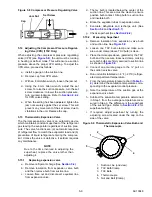
(See
).
e. When refrigerant cylinder scale indicates that the
correct charge has been added, close the liquid
line valve on cylinder and backseat the king valve.
f. Replace all valve caps.
g. Start unit and check for non-condensables.
5.7.3
Adding a Partial Charge
NOTE
When partially charging the refrigeration sys-
tem with R-134A, install a vapor charge.
a. Place refrigerant cylinder on scale and connect
charging line between suction port and refriger-
ant cylinder.
b. Note weight of refrigerant cylinder.
c. Run unit on high speed cool and open cylinder
vapor valve.
d. If necessary, partially block off air flow to con-
denser coil so discharge pressure rises to 174
psig (12 Bars).
e. The unit is correctly charged when there are no
bubbles in the sight glass.
f. Start unit and check for non-condensables.
5.8
Checking for Non-Condensables
To check for non-condensables, proceed as follows:
a. Stabilize system to equalize pressure between
the suction and discharge side of the system.
b. Check temperature at the condenser and receiver.
c. Check pressure at the receiver outlet (King) valve.
d. Check saturation pressure as it corresponds to
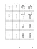
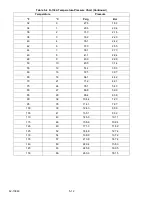
the condenser/receiver temperature using the
Temperature- Pressure Chart,
e. If gauge reading is 3 psig (0.2 Bar) or more than
the calculated P/T pressure in step d., non-con-
densables are present.
f. Remove refrigerant using a refrigerant recovery
)
g. Evacuate and dehydrate the system. (Refer to
)
h. Charge the unit. (Refer to
)
5.9
Replacing the Compressor
5.9.1
Removing Compressor
WARNING
!
Ensure power to the unit is OFF, power
plug is disconnected and circuit breaker
is open or vehicle engine is OFF and neg-
ative battery cable is connected before
replacing compressor.
a. Remove the refrigerant. (See
).
WARNING
!
Slowly open the plug on the suction and
discharge valves of the new compressor
to vent the nitrogen holding charge.
b. Remove bolts from flanges.

