3-1
62-10848
SECTION 3
Operation
3.1
Control System
3.1.1
Introduction
CAUTION
!
Under no circumstances should anyone
attempt to service the microprocessor
module and Cab Command! Should a
problem develop with the control system,
contact your nearest Carrier Transicold
dealer for replacement components.
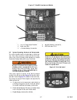
The Control System consists of the microprocessor
module (
), Cab Command (
) and
interconnecting wiring.
• The Microprocessor Module includes the tem-
perature control software and necessary input/
output circuitry to interface with the unit controls.
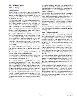
• The Cab Command is remotely mounted in the
truck. The Cab Command includes the LCD dis-
play and keypad. The keypad and display pro-
v i d e u s e r a c c e s s a n d r e a d o u t s o f
microprocessor information. The information is
accessed by keypad selections and viewed on
the display.
3.1.2
Microprocessor Module
The microprocessor controls the following functions:
• Maintains the refrigerated compartment tem-
perature at set point by regulating the cooling,
heat, off mode and automatic defrost cycles.
• Permanently displays the return air temperature
and on request the set point temperature.
• Digital display and selection of data.
For further details on digital message display, see
.
3.1.3
Cab Command
The Cab Command is mounted in the cab and allows
the driver to carry out the control operations:
• Start up and shut-down the unit
• Automatic start-up in road or standby mode
• Adjust the set point
• Defrost
The driver can display the refrigerated compartment
temperature, and see whether the set point is being
maintained by checking the green indicator. The indica-
tor lights up red in the event of a malfunction.
When the battery voltage is too low, a fail-safe system
shuts down the unit. Unit restart is automatic and time-
delayed if the voltage rises to the normal level.
The command consists of the display and the keypad.
The keypad and display serve to provide user access
and readouts of microprocessor information. The infor-
mation is accessed by keypad selections and viewed
on the display.
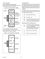
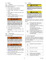
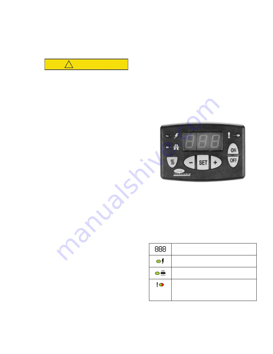
Figure 3.1 Cab Command
a. Display
The digital display consists of three alphanumeric char-
acters. The default value displayed is the refrigerated
compartment temperature. The microprocessor
enables selection of the display in degrees Celsius or
Fahrenheit. The display also includes settings for
defrost operation (dF). The display also includes three
LEDs:
Digital Display
Standby operation LED
Road operation LED
Unit operating LED
• Green: cycling (left-hand side)
• Red: malfunction (right-hand side)


