5-9
62-10848
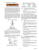
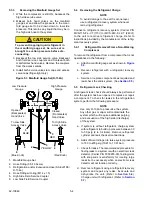
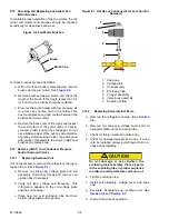
Figure 5.8 Compressor Pressure Regulating Valve
5.14 Adjusting the Compressor Pressure Regulat-
ing Valve (CPR) (115V Only)
When adjusting the compressor pressure regulating
valve (CPR) (see
), the unit must be running
in heating or defrost mode. This will ensure a suction
pressure above the proper CPR setting. To adjust the
CPR valve, proceed as follows:
a. Install a gauge on the suction line.
b. Remove cap from CPR valve.
c. With an 8 mm Allen wrench, loosen the jam nut.
d. Using the 8 mm Allen wrench, adjust the set
screw. To raise the suction pressure, turn the set
screw clockwise; to lower the suction pressure,
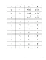
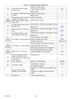
turn counterclockwise. Refer to
for CPR valve setting.
e. When the setting has been adjusted, tighten the
jam nut securely against the set screw. This will
prevent any movement of the set screw due to
vibrations in the unit. Replace the cap.
5.15 Thermostatic Expansion Valve
The thermal expansion valve is an automatic device
which maintains constant superheat of the refrigerant
gas leaving the evaporator regardless of suction pres-
sure. The valve functions are: (a) automatic response
of refrigerant flow to match the evaporator load and (b)
prevention of liquid refrigerant entering the compres-
sor. Unless the valve is defective, it seldom requires
any maintenance.
NOTE
Due to the time involved in adjusting the
superheat, replace the valve rather than
adjusting it.
5.15.1
Replacing expansion valve
a. Remove refrigerant charge (See
b. Remove insulation from expansion valve bulb
and then remove bulb from suction line.
c. Loosen flare nut and disconnect equalizer line
from expansion valve.
d. The txv bulb is located below the center of the
suction line. This area must be clean to ensure
positive bulb contact. Strap bulb to suction line
and insulate both.
e. Braze the equalizer tubes to expansion valve.
f. Evacuate, dehydrate and recharge unit. (See
and
5.15.2
Measuring Superheat
a. Remove insulation from expansion valve bulb
b. Loosen one TXV bulb clamp and make sure
area under clamp (above TXV bulb) is clean.
c. Place thermocouple above (parallel to) the TXV
bulb and then secure loosened clamp making
sure both bulbs are firmly secured to suction line
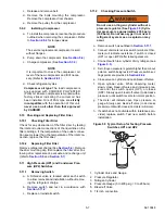
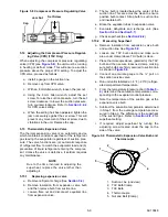
as shown in
d. Connect an accurate gauge to the ¼” port on
the suction service valve.
e. Run unit until stabilized at - 4°F (- 20°C) refriger-
ated compartment temperature.
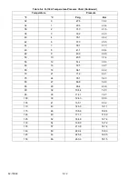
f. From the temperature/pressure chart (
), determine the saturation temperature corre-
sponding to the evaporator outlet pressure.
g. Note the temperature of the suction gas at the
expansion valve bulb.
h. Subtract the saturation temperature determined
in Step f. from the average temperature mea-
sured in Step g. The difference is the superheat
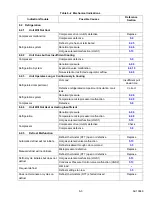
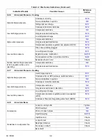
of the suction gas. Refer to
for
superheat setting.
i. If required, adjust superheat by turning the
adjusting screw located under the cap on the
side of the valve.
Figure 5.9
Thermostatic Expansion Valve Bulb and
Thermocouple
1. Suction Line (end view)
2. TXV Bulb Clamp
3. TXV Bulb
4. Thermocouple
5. Nut and Bolt (Clamp)
Set Screw
Jam Nut
Cap

