7-1
62-10848
SECTION 7
Electrical Schematic Wiring Diagram
7.1
Introduction
This section contains electrical schematic wiring diagrams covering the models listed in Table 1-1. The following
general safety notices supplement the specific warnings and cautions appearing elsewhere in this manual. They
are recommended precautions that must be understood and applied during operation and maintenance of the
equipment covered herein.
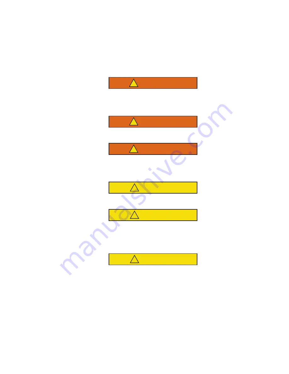
WARNING
!
Beware of unannounced starting of the unit. The unit may cycle the fans and operating com-
pressor unexpectedly as control requirements dictate. Press OFF key on the cab command
and disconnect power plug.
WARNING
!
Under no circumstances should ether or any other starting aids be used to start engine.
WARNING
!
Under no circumstances should anyone attempt to repair the microprocessor module or Cab
Command! Should a problem develop with these components, contact your nearest Carrier
Transicold dealer for replacement.
CAUTION
!
proper polarity when installing battery, negative battery terminal must be grounded.
CAUTION
!
Under no circumstances should a technician electrically probe the processor at any point,
other than the connector terminals where the harness attaches. Microprocessor components
operate at different voltage levels and at extremely low current levels. Improper use of voltme-
ters, jumper wires, continuity testers, etc. could permanently damage the processor.
CAUTION
!
Most electronic components are susceptible to damage caused by electrical static discharge
(ESD). In certain cases, the human body can have enough static electricity to cause resultant
damage to the components by touch. This is especially true of the integrated circuits found on
the microprocessor. Use proper board handling techniques. (See Section 4.17).
7.2
Wiring Schematic
Refer to
on the following pages

