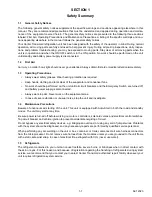
background image

62-12023

1-2

1.6

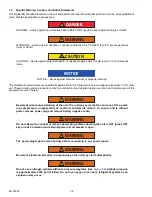
Specific Warning, Caution, and Notice Statements

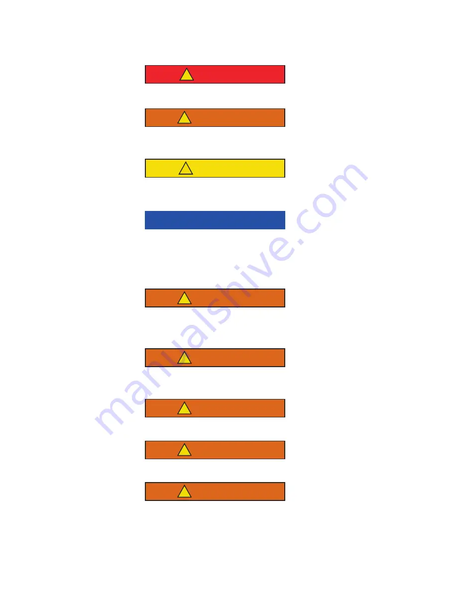
To help identify the label hazards on the unit and explain the level of awareness each one carries, an explanation is
given with the appropriate consequences:

DANGER

!

DANGER 

 warns against an immediate hazard which WILL result in severe personal injury or death. 

WARNING

!

WARNING 

 warns against hazards or unsafe conditions which COULD result in severe personal

injury or death.

CAUTION

!

CAUTION 

 warns against potential hazard or unsafe practices which could result in minor personal

injury.

NOTICE

NOTICE 

 warns against potential product or property damage. 

The statements listed below are specifically applicable to this refrigeration unit and appear elsewhere in this man-
ual. These recommended precautions must be understood and applied during operation and maintenance of the
equipment covered herein

.

WARNING

!

Beware of unannounced starting of the unit. The unit may cycle the fans and one of the operat-
ing compressors unexpectedly as control requirements dictate. To ensure unit is without
power, remove power plug and remove battery negative cable.

WARNING

!

Do not attempt to connect or remove power plug before ensuring the unit is OFF (press OFF
key on Cab Command) and external power circuit breaker is open.

WARNING

!

The power plug must be clean and dry before connecting to any power source.

WARNING

!

Beware of V-belt and belt-driven components as the unit may start automatically.

WARNING

!

Do not use a nitrogen cylinder without a pressure regulator. (See 

Figure 5.4

) Cylinder pressure

is approximately 2350 psi (160 Bar). Do not use oxygen in or near a refrigerant system as an
explosion may occur.

Summary of Contents for Integra 35X

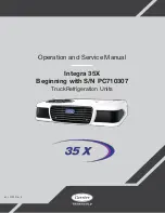
Page 1: ...Operation and Service Manual Integra 35X Beginning with S N PC710307 TruckRefrigeration Units 62 12023 Rev E ...

Page 2: ......

Page 3: ...Operation and Service For Integra 35X Beginning with S N PC710307 Truck Refrigeration Units 2020 Carrier Corporation Printed in USA May 2020 ...

Page 4: ...R back into line dlr C 10 24 2018 Updated path of flow drawings pages 2 11 2 12 2 13 removed reference to alarms A46 and A47 in several sections dlr D 4 28 2020 Updated covers and logo E 5 8 2020 Section 2 3 Remove ref to filter drier change to drier receiver Section 3 8 updated configuration list Sections 5 3 5 3 1 Remove ref to filter drier Section 5 5 2 Remove step 4 Step 5 5 3 Remove first sen...

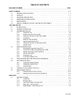
Page 5: ...8 Standby Motor 2 5 2 4 EVAPORATOR SECTION 2 5 2 4 1 Thermostatic Expansion Valve TXV 2 5 2 4 2 Compressor Pressure Regulating Valve CPR 2 5 2 4 3 Defrost Termination Thermostat DTT 2 5 2 4 4 Quench Valve BPV 2 5 2 4 5 Evaporator Coil 2 6 2 4 6 Low Pressure Switch LP 2 6 2 5 SYSTEM OPERATING CONTROLS AND COMPONENTS 2 6 2 6 UNIT SPECIFICATIONS 2 7 2 6 1 Compressor Reference Data 2 7 2 6 2 Refrigera...

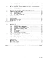
Page 6: ... STOPPING THE UNIT 3 14 TEMPERATURE CONTROL 4 1 4 1 SEQUENCE OF OPERATION 4 1 4 1 1 Cooling Mode 4 1 4 1 2 Heating Mode 4 1 4 1 3 Frozen Mode 4 2 4 2 DEFROST CYCLE 4 2 4 3 MINIMUM OFF TIME 4 2 SERVICE 5 1 5 1 MAINTENANCE 5 1 5 2 INSTALLING R 404A MANIFOLD GAUGE SET 5 2 5 2 1 Preparing Manifold Gauge Hose Set for Use 5 3 5 2 2 Connecting Manifold Gauge Hose Set 5 3 5 2 3 Removing the Manifold Gauge...

Page 7: ...PROCESSOR 5 14 5 16 EVAPORATOR COIL CLEANING 5 14 5 17 CONDENSER COIL CLEANING 5 15 TROUBLESHOOTING 6 1 6 1 INTRODUCTION 6 1 6 2 REFRIGERATION 6 4 6 2 1 Unit Will Not Cool 6 4 6 2 2 Unit Runs But Has Insufficient Cooling 6 4 6 2 3 Unit Operates Long or Continuously in Cooling 6 4 6 2 4 Unit Will Not Heat or Heating Insufficient 6 4 6 2 5 Defrost 6 4 6 2 6 Abnormal Pressure 6 5 6 2 7 Abnormal Noise...

Page 8: ......

Page 9: ...ork should be performed on the unit until all circuit breakers and the Emergency Switch are turned off and battery power supply is disconnected Always work in pairs Never work on the equipment alone In case of severe vibration or unusual noise stop the unit and investigate 1 4 Maintenance Precautions Beware of unannounced starting of the unit This unit is equipped with Auto Start in both the road ...

Page 10: ...s man ual These recommended precautions must be understood and applied during operation and maintenance of the equipment covered herein WARNING Beware of unannounced starting of the unit The unit may cycle the fans and one of the operat ing compressors unexpectedly as control requirements dictate To ensure unit is without power remove power plug and remove battery negative cable WARNING Do not att...

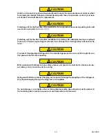
Page 11: ...ature or if Owners operating parameters have changed the Configuration will need to be reset CAUTION To prevent trapping liquid refrigerant in the manifold gauge set be sure set is brought to suc tion pressure before disconnecting CAUTION When working with refrigerant use safety glasses and gloves to avoid burns Hoses and cop per tubing can be hot when unit is running CAUTION Refrigerant R 404A is...

Page 12: ......

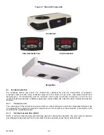
Page 13: ... driven by the engine of the vehicle when in operation over the road Road Standby operation With the standby option a second compressor is mounted in the condenser sec tion This compressor is driven by 115 1 60Hz or 230 1 60Hz or 230 3 60Hz power The control system is a microprocessor controller Once the controller is set at the desired temperature the system automatically selects cooling and heat...

Page 14: ...e units are fitted with a start box which contains the capacitors and relay 2 3 1 Condenser Coil The condenser is of the microchannel type and acts as a heat exchanger in which the compressed refrigerant gas is condensed into a liquid and lowered in temperature Air movement over the condenser is provided by a fan mounted in the condensing section 2 3 2 Hot Gas Solenoid Valve HGS1 HGS1 is normally ...

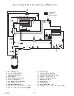
Page 15: ... Sight Glass 4 Frame Assembly 5 Standby Compressor 6 Microprocessor 7 Hot Gas Valve HGS1 and Coil 8 Oil Separator 9 Condenser Coil 10 Condenser Pressure Control Valve HGS2 Coil 11 Rectifier 12 Transformer 4 6 7 8 9 10 1 2 3 Road Only Road Standby 1 2 3 8 7 10 9 4 5 12 11 ...

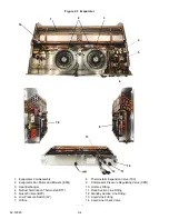
Page 16: ...ost Termination Thermostat DTT 5 Quench Valve BPV 6 Low Pressure Switch LP 7 Orifice 8 Thermostatic Expansion Valve TXV 9 Compressor Pressure Regulating Valve CPR 10 Hot Gas Fitting 11 Road Suction Line Fitting 12 Standby Suction Line Fitting 13 Liquid Line Fitting 14 Liquid Line Check Valve 1 2 3 4 5 6 7 8 9 13 12 11 10 14 ...

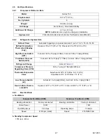
Page 17: ...harge pressure for heating capacity For HP2 settings see Section 2 6 2 2 3 8 Standby Motor The standby motor operates on nominal 115 230V 1ph 60Hz or 230V 3ph 60Hz power An overload and short cycle protection is provided along with automatic reset Units are also equipped with a remote mounted power receptacle 2 4 Evaporator Section The evaporator assembly see Figure 2 1 and Figure 2 3 consists of ...

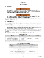
Page 18: ...ols and Components The unit is furnished with a microprocessor control system Once the setpoint is entered at the Cab Command the unit will operate automatically to maintain the desired temperature within very close limits See Section 3 1 1 WARNING Beware of unannounced starting of the unit The unit may cycle the fans and one of the operat ing compressors unexpectedly as control requirements dicta...

Page 19: ... F 27 3 C Closes at 40 5 F 22 2 3 C High Pressure Switch HP1 Cutout at 465 10 psig 32 Bar Cut in at 360 10 psig 25 Bar Condenser Pressure Switch HP2 Cutout at 245 10 psig1 17 Bar Cut in at 320 10 psig 22 Bar Refrigerant Charge Refer to Table 2 1 Compressor Pressure Regulating Valve CPR 30 5 1 psig 2 1 Bar 2400 rpm Thermostat Expansion Valve Superheat at 32 F 0 C Box 14 5 F 8 C Superheat at 0 F 20 ...

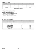
Page 20: ...nce 7 2 Ω f Quench Valve BPV Coil Amp Draw 1160 mAmp Resistance 10 3 Ω 2 7 Torques Values Safety Devices Voltage kW HP Contactor Data MRA 115 1 60Hz 1 5 2 23 2A 230 1 60Hz 11 7A 230 3 60Hz 8 9A MRA Maximum Rotor Amps Assembly Ft Lbs N m Standby compressor platform 40 7 5 Standby motor platform 40 7 5 Standby motor pulley 40 7 5 Compressor pulley 22 29 8 Evaporator fan motor 13 17 6 Condenser frame...

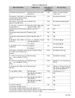
Page 21: ...ection error on primary transformer F1 115 1 60 NO 8A Time Delayed F1 230 1 60 5A Time Delayed F1 230 3 60 10 Excessive compressor motor or standby motor winding tem perature Internal Thermal Overload YES Self protected opening 11 Clutch not functioning prop erly road excessive current draw Electronic relay YES Self protected opening 12 Clutch not functioning prop erly road insufficient current dr...

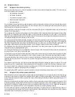
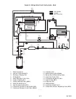
Page 22: ...o the suction gas The liquid than enters the thermostatic expansion valve with external pressure equalizer which regulates the flow rate of refrigerant towards the evaporator in order to obtain maximum use of the evaporator heat transfer surface The evaporator tubes have aluminum fins to increase heat transfer therefore heat is removed from the air circu lated through the evaporator This cold air ...

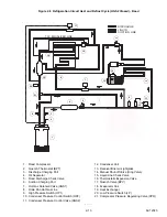
Page 23: ...Pressure Control Switch HP2 11 Condenser Pressure Control Valve HGS2 12 Condenser Coil 13 Receiver Drier with sightglass 14 Manual Shut off Valve King Valve 15 Liquid Line Check Valve 16 Thermostatic Expansion Valve 17 Quench Valve BPV 18 Evaporator Coil 19 Heat Exchanger 20 Low Pressure Switch LP 21 Compressor Pressure Regulating Valve CPR TXV EQUALIZER LINE DISCHARGE LIQUID SUCTION LINE 1 1 2 2 ...

Page 24: ...rol Switch HP2 11 Condenser Pressure Control Valve HGS2 12 Condenser Coil 13 Receiver Drier w sightglass 14 Manual Shut off Valve King Valve 15 Liquid Line Check Valve 16 Thermostatic Expansion Valve 17 Quench Valve BPV 18 Evaporator Coil 19 Heat Exchanger 20 Low Pressure Switch LP 21 Compressor Pressure Regulating Valve CPR TXV EQUALIZER LINE DISCHARGE LIQUID SUCTION LINE TXV EQUALIZER LINE DISCH...

Page 25: ...0 Condenser Pressure Control Switch HP2 11 Condenser Pressure Control Valve HGS2 12 Condenser Coil 13 Receiver Drier w sightglass 14 Manual Shut off Valve King Valve 15 Liquid Line Check Valve 16 Thermostatic Expansion Valve 17 Quench Valve BPV 18 Evaporator Coil 19 Heat Exchanger 20 Low Pressure Switch LP 21 Compressor Pressure Regulating Valve CPR TXV EQUALIZER LINE DISCHARGE LIQUID SUCTION LINE...

Page 26: ...essure Switch HP1 12 Condenser Pressure Control Switch HP2 13 Condenser Pressure Control Valve HGS2 14 Condenser Coil 15 Receiver Drier w sightglass 16 Manual Shut off Valve King Valve 17 Liquid Line Check Valve 18 Thermostatic Expansion Valve 19 Quench Valve BPV 20 Evaporator Coil 21 Heat Exchanger 22 Low Pressure Switch LP 23 Compressor Pressure Regulating Valve CPR 7 9 TXDOL HU LQH 1 1 3 3 2 2 ...

Page 27: ... Line 11 High Pressure Switch HP1 12 Condenser Pressure Control Switch HP2 13 Condenser Pressure Control Valve HGS2 14 Condenser Coil 15 Receiver Drier w sightglass 16 Manual Shut off Valve King Valve 17 Liquid Line Check Valve 18 Thermostatic Expansion Valve 19 Quench Valve BPV 20 Evaporator Coil 21 Heat Exchanger 22 Low Pressure Switch LP 23 Compressor Pressure Regulating Valve CPR 7 9 TXDOL HU ...

Page 28: ... 11 High Pressure Switch HP1 12 Condenser Pressure Control Switch HP2 13 Condenser Pressure Control Valve HGS2 14 Condenser Coil 15 Receiver Drier w sightglass 16 Manual Shut Off Valve King Valve 17 Liquid Line Check Valve 18 Thermostatic Expansion Valve 19 Quench Valve BPV 20 Evaporator Coil 21 Heat Exchanger 22 Low Pressure Switch LP 23 Compressor Pressure Regulating Valve CPR 7 9 TXDOL HU LQH 1...

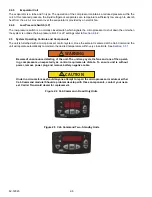
Page 29: ...and automatic defrost cycles Displaying the return air temperature permanently and on request the setpoint temperature Enabling the operator to digitally display and select data For further details on digital message display see Section 3 1 4 or Section 3 1 5 3 1 3 Cab Command Cab Command Two The Cab Command is mounted in the cab of the truck The Cab Command includes the LCD display and keypad The...

Page 30: ...ill indicate the temperature control status Refer to Figure 3 2 for more detail Red Light Status When an alarm has been detected the red unit indicating light flashes at 1 Hz The light will continue to flash at 1 Hz until the alarm is cleared At that point the steady green indica tor light will light and the alarm will become inactive Figure 3 2 Green Light Status Digital Display Standby operation...

Page 31: ...tion of the display in degrees Celsius or Fahrenheit The display also includes sentines for defrost operation dF and three LEDs Manual defrost control key Unit start up key Unit shut down key The unit can also be shut down with the ignition key The SET key together with the and keys enables display and modification of unit operating data The display scrolls through parameters each time the SET key...

Page 32: ...inactive When the unit has been running for at least 15 minutes after setpoint has been reached and goes out of range the red LED will flash Refer to Fig ure 3 5 for more detail Figure 3 4 Green Light Status Figure 3 5 Red Light Status Press the Unit start up key to turn on the unit Press the key during the first five seconds to decrease the display brightness Press the key during the first five s...

Page 33: ... Manual defrost control key Unit start up key Unit shut down key in standby or road mode In road operation the unit can also be shut down with the ignition key The SET key together with the and keys enables display and modification of unit operating data The display changes parameters each time the SET key is pressed Decrease key for selected data Increase key for selected data 1 Press SET for fiv...

Page 34: ... Start the vehicle engine 2 Press the ON key to start the unit After a 40 second delay the unit starts up The digital display of the Cab Command displays the box temperature 3 Press the SET key and then check that temperature setpoint is correct The setpoint temperature is high lighted on the digital display 3 2 3 Starting Road Standby Units Cab Command Two 1 Depending on desired mode of operation...

Page 35: ...onds HGS1 ON pressure equalization c 40 seconds MC ON Standby contactor coil d 50 seconds HGS1 OFF fans ON unit in cool Start up on Road with heat setpoint and box temp 5 F 20 6 C a 0 time ON key pushed b 20 seconds HGS1 HGS2 CLHR ON c 45 seconds fans BPV ON unit in heat Start up on Standby with heat setpoint and box temp 5 F 20 6 C a 0 time ON key pushed b 10 seconds HGS1 HGS2 ON c 20 seconds MC ...

Page 36: ...interval timer is reset to zero when the defrost cycle is terminated a Manual Defrost 1 Check that box temperature is 40 F 4 4 C or lower 2 Press the MANUAL DEFROST key to initiate manual defrost b Defrost Termination Safety If the defrost cycle does not terminate after 45 minutes the cycle terminates automatically and displays alarm code A14 3 5 Alarm Display In the event of an alarm the unit wil...

Page 37: ...02 High or Low pressure switch X A01 Low pressure switch LP X A02 High pressure switch X A03 Standby compressor thermal overload open X X A04 Road compressor clutch CLHR not functioning properly X A05 Standby contactor MC high amp draw X X A06 Condenser fan motor CFM high amp draw X X A07 Evaporator Fan low rotational speed A08 Not applicable X X A09 Hot gas valve HGS1 high amp draw X X A10 Quench...

Page 38: ...e display to Fahrenheit the selection jumper must be removed and discarded 2 Press the Unit shut down key to turn off the unit 3 The following steps must be performed with the unit OFF a Hold both DEFROST and ON keys momentarily in order to display parameters b Use the and keys to modify parameters as needed c Press the SET key to confirm a change NOTE If no buttons are depressed within five secon...

Page 39: ...aporator fan is displayed next This feature determines whether the evaporator fan is on or off when the unit cycles off upon reaching setpoint The factory setting is OFF Change setting by using the or keys Selection MUST be validated by pressing the SET key The return air temperature will be displayed after the above sequence 3 7 2 Road Standby Units Cab Command Two The procedure for adjusting the...

Page 40: ...he time factoring in length of last defrost time between two defrost cycles in relation to setpoint and cargo 0 5 to 0 9 decreases the microprocessor calculated time between defrosts by 1 2 normal to 9 10 normal 1 1 to 1 5 increases the microprocessor calculated time between defrosts by 1 1 times normal to 1 1 2 times normal 1 H 2 H 6 H Forced interval between each defrost expressed in hours 3 8 M...

Page 41: ... and go to the next configuration Optional Road Heating Kit hrOF option road heating kit not installed hrOn option road heating kit installed 1 Press the or keys to change hrOF or hrOn 2 Press the SET key to validate and go to the next configuration Optional Standby Heat Kit hSOF standby heating kit not installed hSOn standby heating kit installed 1 Press the or keys to change hrOF or hrOn 2 Press...

Page 42: ...ange the setting to desired selection 2 Press the SET key to validate and go to the next configuration Pump Down option PdOF Pump down option disactivated PdON Pump down option activated 1 Press the or keys to change the setting to desired selection 2 Press the SET key to validate and go to the next configuration If Pump Down option is activated the following 2 configurations are then available Co...

Page 43: ... the BPT the thermostat will open DE energiz ing the BPV c Once temperature decreases to the setpoint the unit will enter the null mode If the continuous air flow parameter is set to ON the evaporator fans will continue to operate with all other components OFF If the continuous air flow parameter is OFF the evaporator fans and all other components will be OFF A five min ute delay is required befor...

Page 44: ...t the evaporator fans shut down and operation of the condenser fan is controlled by the microproces sor For road only units the end of the defrost cycle is time based only For standby units the end of the cycle is controlled by the opening of the defrost termination thermostat See Section 2 6 2 for DTT settings The same logic for component control that applies to heating also applies to defrost Se...

Page 45: ...egory are provided in Table 5 5 Table 5 1 Maintenance After Start up Check condenser and evaporator fan rotation and proper air flow Check cab command for proper unit cycling and correct display of all indicator lights Check for unusual noise or vibration Check that refrigerant is visible in liquid line sight glass Table 5 2 Maintenance After 15 Minutes or More of Operation Check that refrigerant ...

Page 46: ...kit is correctly tightened and the belt tension is cor rect 3 Check the tightness of bolts and screws and that the unit is correctly fas tened onto the box 4 Check tension of alternator compressor belt Service B 1 Clean condenser and the evaporator coils Section 5 16 and Section 5 17 2 Replace the road compressor belt 3 Check and if required replace the filter drier Section 5 8 4 Check the operati...

Page 47: ...nd valves and disconnect from cylinder The gauge set is now ready for use 5 2 2 Connecting Manifold Gauge Hose Set To connect the manifold gauge hose set for reading pressures do the following 1 Remove service valve stem cap and check that it is backseated Remove access valve cap 2 Connect the refrigeration hose see Figure 5 1 to the access valve 3 Read system pressures 4 Repeat the procedure to c...

Page 48: ... 2 Open valves two turns clockwise Purge gauge line 3 Close the receiver outlet king valve by turning clockwise Start unit and run in high speed cooling Place Run stop switch in the STOP position when unit reaches 0 1 kg cm2 1 psig 4 Frontseat close suction service valve and the refrigerant will be trapped between the compressor suction service valve and the manual shutoff King valve 5 Before open...

Page 49: ... refrigerant leak check refer to Section 5 4 and evacuate and dehydrate the low side refer to Section 5 6 8 Check refrigerant charge refer to Section 5 6 1 5 4 Refrigerant Leak Checking CAUTION Refrigerant R 404A is a blend Charging as a vapor will change the properties of the refrigerant Only liquid charging through the king valve is acceptable NOTE Only refrigerant 404A should be used to pressur...

Page 50: ...e and dehydrate the system is to connect three evacuation hoses to the vacuum pump and refrigeration unit as shown in Figure 5 2 do not use standard service hoses as they are not suited for evacuation purposes Connect an evacuation manifold with special evacuation hoses to the vacuum pump to the electronic vacuum gauge and to the refrigerant recovery system 3 Test the evacuation system for leaks b...

Page 51: ... Close off vacuum pump valve and stop pump Wait five minutes to see if vacuum holds This checks for residual mois ture and or leaks 10 With a vacuum still in the unit the refrigerant charge may be drawn into the system from a refrigerant con tainer on weight scales See Table 2 1 for correct charge Continue to Section 5 6 2 5 6 Charging the Refrigeration System CAUTION Refrigerant R 404A is a blend...

Page 52: ...uge set to the manifold dead head port Connect a charging line between the center tap of the second gauge set and the refrigerant drum Midseat discharge knob Open the liquid valve on the drum and purge all hoses Frontseat discharge knob See Figure 5 3 3 Note weight of refrigerant cylinder 4 Open liquid valve on refrigerant cylinder Open king valve half way and allow the liquid refrigerant to flow ...

Page 53: ... Remove refrigerant charge see Section 5 3 Remove the drier mounting clip then replace the filter drier Follow ing drier replacement evacuate and recharge unit refer to Section 5 5 and Section 5 6 5 9 High Condenser and Low Pressure Control Switch HP1 HP2 LP 5 9 1 Removing Switches 1 A schraeder valve is located under each switch to allow removal and installation without removing the refrig erant ...

Page 54: ...P2 and LP 1 Cylinder valve and gauge 2 Pressure regulator 3 Nitrogen cylinder 4 Pressure gauge 0 to 400 psig 0 to 28 Bars 5 Bleed off valve 6 1 4 inch connection 5 10 Hot gas Condenser and Low Pressure Control Switch HGS1 HGS2 BPV 5 10 1 Replacing Solenoid Coil It is not necessary to remove the refrigerant charge when replace the coil see Figure 5 5 Figure 5 5 Hot Gas Valve Condenser Pressure Cont...

Page 55: ...nclosing tube If valve has been removed from the circuit check for leaks 6 Install coil assembly voltage cover and snap cap 7 Evacuate dehydrate and recharge unit Refer to paragraphs Section 5 5 3 and Section 5 6 2 8 Start unit and check operation 5 11 Adjusting the Compressor Pressure Regulating Valve CPR When adjusting the compressor pressure regulating valve CPR see Figure 5 6 the unit must be ...

Page 56: ...ine 3 Loosen inlet nut and unbraze equalizer line and outlet line from expansion valve 4 The thermal bulb is located below the center of the suction line This area must be clean to ensure positive bulb contact Strap thermal bulb to suction line and insulate both 5 Braze the equalizer tubes to expansion valve 6 Evacuate dehydrate and recharge unit 7 Check superheat refer to Section 2 6 2 5 12 2 Mea...

Page 57: ... of the cable into the primary tool and the other end into the remote tool 4 Begin the test by turning on the power switch and observing the sequence of green lights As each circuit is tested the corresponding light is illuminated If a fault is found in the cable the light that corresponds to that particular circuit is not illuminated 5 To test a cable that is not installed on a unit simply plug e...

Page 58: ...h a mild detergent solution such as any good commercial grade automatic dish washer deter gent and let the solution stand for a few minutes Reverse flush opposite normal air flow with clean water at mild pressure A garden hose with spray nozzle is usually sufficient All drain lines must be clean 2 Run unit until defrost mode be initiated to check for proper draining from drain pan 5 17 Condenser C...

Page 59: ... 96 2 6 76 6 63 48 9 99 9 7 02 6 89 50 10 103 7 7 29 7 15 55 13 115 4 8 11 7 96 60 16 126 1 8 87 8 69 65 18 137 4 9 66 9 47 70 21 149 4 10 50 10 30 75 24 162 1 11 40 11 18 80 27 175 5 12 34 12 10 85 29 189 6 13 33 13 07 90 32 204 5 14 38 14 10 95 35 220 2 15 48 15 18 100 38 236 8 16 65 16 33 105 41 254 2 17 87 17 53 110 43 272 4 19 15 18 78 115 46 291 6 20 50 20 11 120 49 311 8 21 92 21 50 125 52 ...

Page 60: ...9 165 300 10 23 3 117 800 0 17 8 85 500 10 12 2 62 400 20 6 7 46 300 30 1 1 34 500 32 0 32 700 40 4 4 26 200 50 10 0 19 900 60 15 6 15 300 70 21 1 11 900 77 25 10 000 80 26 7 9 300 90 32 2 7 300 100 37 8 5 800 110 43 3 4 700 120 48 9 3 800 194 90 915 212 100 680 266 130 301 302 150 186 Table 5 6 R 404A Temperature Pressure Chart Continued Temperature Pressure F C Psig Kg cm2 Bar ...

Page 61: ... drier restricted Section 5 8 1 TXV strainer plugged with foreign material ice Section 5 12 TXV not functioning properly Section 5 12 Verify operation of evaporator fans Failed switch Section 5 9 2 High Pressure Switch HP1 Open Unit overcharged Section 5 6 1 Verify operation of condenser fan Noncondensibles in system Section 5 8 Failed switch Section 5 9 2 A01 Low Pressure Switch LP Open Road Unit...

Page 62: ...0 1 A11 Condenser Pressure Control Valve HGS2 high amp draw Current draw of coil high or low approx 1 6 amp Replace coil Section 5 10 1 A12 Out of Range High Temperature Unit out of range for 15 minutes Verify Setting Verify cooling operation of unit Hot gas solenoid open Section 5 10 A13 Out of Range Low Temperature Unit out of range for 15 minutes Verify Setting Verify heating operation of unit ...

Page 63: ...26 Condenser Pressure Control Valve HGS2 Open Circuit Valve coil shorted Section 5 10 1 Wiring to coil open Correct A27 Evaporator Drain Line Heater DWR Open Circuit Evaporator drain heater shorted Replace Verify wiring to heater Correct A28 Heating Relay EHR Open Circuit Future Relay open circuit Replace Wiring to coil open Correct A45 EPROM Failure Disconnect Reconnect cables to vehicle battery ...

Page 64: ...ller not functioning properly Section 6 2 6 Section 6 2 8 Compressor Defective Replace 6 2 4 Unit Will Not Heat or Heating Insufficient Refrigeration Abnormal pressure Temperature controller not functioning properly Hot gas solenoid not functioning properly HGS1 Section 6 2 6 Section 6 2 8 Section 5 10 Compressor Compressor drive clutch defective Compressor defective Check Replace 6 2 5 Defrost Au...

Page 65: ...noid not functioning properly Replace Section 5 10 Heating High discharge pressure Overcharged system Condenser fan or HP2 pressure switch defective Noncondensibles in system Condenser motor fan defective HGS2 closed Section 5 6 1 Section 5 9 Section 5 6 Section 5 16 Low discharge pressure Compressor defective Hot gas valve not functioning properly Replace Section 5 10 Low suction pressure Low ref...

Page 66: ...lb Low superheat setting Section 5 12 Replace Section 5 12 2 High superheat Expansion valve setting Section 5 12 2 6 3 2 Hot Gas Solenoid or Condenser Pressure Regulating Valve Valve does not function properly No power to valve Improper wiring or loose connections Valve improperly assembled Coil or coil sleeve improperly assembled Movement of plunger restricted due to a Corroded or worn parts b Fo...

Page 67: ...e unit is without power remove power plug and remove battery negative cable CAUTION Under no circumstances should anyone attempt to service the microprocessor see Section 5 15 or either Cab Command Module Should a problem develop with the microprocessor con tact your nearest Carrier Transicold dealer for replacement 7 1 Introduction Schematic diagrams for the unit models listed in Table 2 1 are pr...

Page 68: ......

Page 69: ...wiring schematics ...

Page 70: ......

Page 71: ...wiring schematics ...

Page 72: ......

Page 73: ...wiring schematics ...

Page 74: ......

Page 75: ...wiring schematics ...

Page 76: ......

Page 77: ...ermination Thermostat DTT 2 5 Diagnostic Tool 5 14 E Electrical Data 2 7 Evacuation and Dehydration 5 5 General 5 5 Preparation 5 6 Procedure for Complete System 5 6 Evaporator Coil 2 6 Evaporator Coil Cleaning 5 14 Evaporator Section 2 5 F First Aid 1 1 Frozen Mode 4 2 G General Description 2 1 General Safety Notices 1 1 H Heating Mode 4 1 High Pressure Switch HP1 2 5 5 9 Hot Gas Solenoid Valve H...

Page 78: ... 5 5 12 Checking the Orifice Strainer 5 14 Measuring Superheat 5 13 Replacing 5 13 Torques Values Safety Devices 2 8 Troubleshooting Alarm Indications 6 1 Troubleshooting Evaporator Air Flow Problems 6 6 Expansion Valve 6 6 Malfunction Hot Gas Solenoid 6 6 Malfunction Standby Compressor 6 6 Troubleshooting Refrigeration Problems 6 4 Abnormal Noise 6 5 Abnormal Pressure 6 5 Cab Command Malfunction ...

Page 79: ......
Page 80: ... A Piso 5 Colonia Anahuac 11320 Mexico D F WARNING Breathing diesel engine exhaust exposes you to chemicals known to the State of California to cause cancer and birth defects or other reproductive harm Always start and operate engine in a well ventilated area If in an enclosed area vent the exhaust to the outside Do not modify or tamper with the exhaust system Do not idle the engine except as nece...

Reviews: