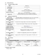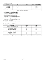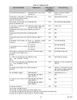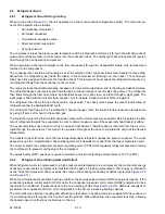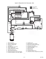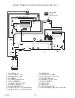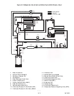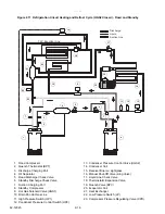
2-1
62-12023
SECTION 2
Unit Description
2.1
Introduction
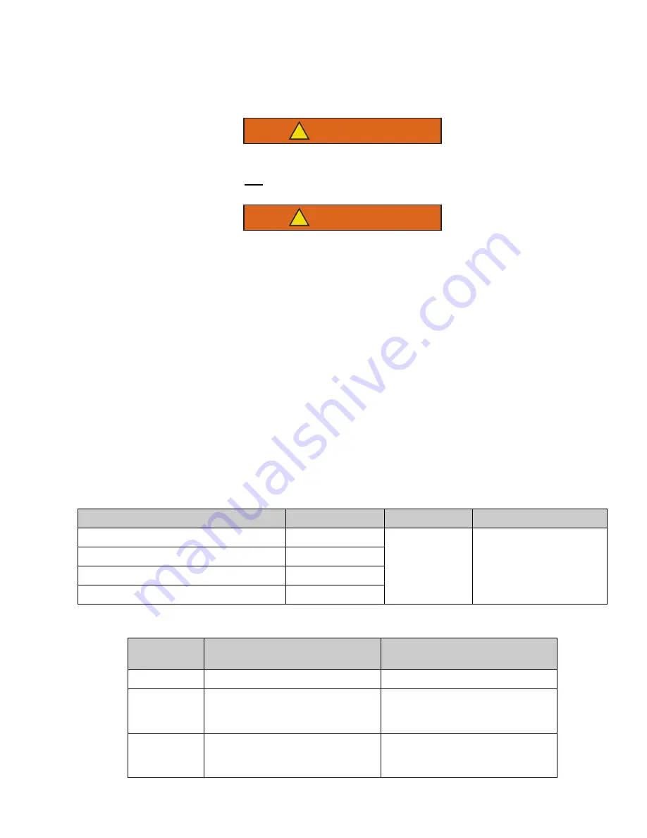
WARNING
!
Beware of unannounced starting of the unit. The unit may cycle the fans and one of the operat-
ing compressors unexpectedly as control requirements dictate. To ensure unit is without
power, remove power plug and remove battery negative cable.
WARNING
!
Do not attempt to connect or remove power plug before ensuring the unit is OFF (press OFF
key on Cab Command) and external power circuit breaker is open.
This manual contains operating data, electrical data, and service instructions for the Carrier Transicold 35X truck
refrigeration units listed in
2.2
General Description
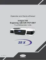
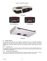
The 35X unit (
) is of the split system type with the condenser mounted outside the truck body, evaporator
mounted in the body, and a Cab Command controller mounted in the drivers compartment. Two types of compres-
sor drives are available:
•
Road operation
: The compressor is driven by the engine of the vehicle when in operation over-the-road.
•
Road/Standby operation
: With the standby option a second compressor is mounted in the condenser sec-
tion. This compressor is driven by 115/1/60Hz or 230/1/60Hz or 230/3/60Hz power.
The control system is a microprocessor controller. Once the controller is set at the desired temperature, the system
automatically selects cooling and heating cycles as necessary to maintain the desired temperature within very
close limits.
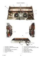
The model/serial nameplate is located inside the unit on the frame as shown in
Table 2–1 Model Chart
Model
Voltage
R-404A
Compressor
Road Only TRC135R03D
12V, No Standby
3.3 lb (1.5 KG)
Series 150
Road and Standby TRS135R53D
115/1/60
Road and Standby TRS135R13D
230/1/60
Road and Standby TRS135R23D
230/3/60
Table 2–2 Additional Support Manuals
Manual
Number
Equipment Covered
Type of Manual
62-12032
35X
Parts List
62-10892
20X & 35X Road Only Truck Refrig-
eration Units with Cab Command
Controller
Operator’s Manual
62-11045
35X with Standby & 40/50X Truck
Refrigeration Units with Cab
Command Two Controller
Operator’s Manual
Summary of Contents for Integra 35X
Page 2: ......
Page 8: ......
Page 12: ......
Page 68: ......
Page 69: ...wiring schematics ...
Page 70: ......
Page 71: ...wiring schematics ...
Page 72: ......
Page 73: ...wiring schematics ...
Page 74: ......
Page 75: ...wiring schematics ...
Page 76: ......
Page 79: ......

