2-5
62-12023
2.3.3
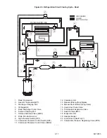
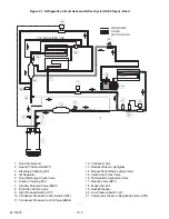
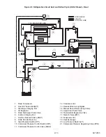
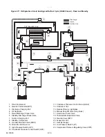
Condenser Pressure Control Valve (HGS2)
The condenser pressure control valve (or condenser closing valve) is a normally open valve that is powered when the
condenser pressure control switch (HP2) is closed. With the solenoid coil de-energized, the valve is in the cool mode
and the compressor discharge gas is delivered to the condenser. In the cool mode, heat is removed from the air
inside the truck body and rejected to the surrounding air. With the solenoid coil energized, the valve is in the heat
mode and the compressor discharge gas is diverted to the evaporator and rejected to the air inside the truck body.
2.3.4
Compressor
The compressor withdraws refrigerant gas from the evaporator and delivers it to the condenser at an increased pres-
sure. The pressure is such that refrigerant heat can be absorbed by the surrounding air at ordinary temperatures.
2.3.5
Receiver / Drier Assembly
Liquid refrigerant from the condenser is delivered to the receiver. The receiver serves as a liquid reservoir when
there are surges due to load changes in the system, as a storage space when pumping down the system and as a
liquid seal to prevent refrigerant gas from entering into the liquid line.
The drier is a cylindrical shell containing a drying agent and screen. The drier is installed in the liquid line and func-
tions to keep the system clean and remove moisture from the refrigerant.
2.3.6
High Pressure Switch (HP1)
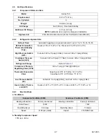
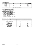
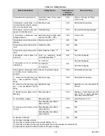
HP1 is a normally closed switch which monitors the system for high pressure and shuts down the unit when pres-
sure
rises above a predetermined setting
. For HP1 settings see
.
2.3.7
Condenser Pressure Control Switch (HP2)
HP2 is a normally open switch which closes to signal the microprocessor to activate the condenser fan. HP2 also
cycles the condenser pressure control valve (HGS2) and the quench valve (BPV) in addition to the condenser fan
in order to maintain discharge pressure for heating capacity. For HP2 settings see
.
2.3.8
Standby Motor
The standby motor operates on nominal 115/230V-1ph-60Hz or 230V-3ph-60Hz power. An overload and short
cycle protection is provided along with automatic reset. Units are also equipped with a remote mounted power
receptacle.
2.4
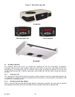
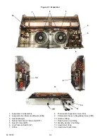
Evaporator Section
and
) consists of two evaporator blowers, the evaporator coil,
thermostatic expansion valve, defrost termination thermostat, compressor pressure regulating valve, low pressure
switch and quench valve.
2.4.1
Thermostatic Expansion Valve (TXV)
The thermostatic expansion valve is an automatic device which controls the flow of liquid to the evaporator accord-
ing to changes in superheat of the refrigerant leaving the evaporator. The thermal expansion valve maintains a rel-
atively constant degree of superheat in the gas leaving the evaporator regardless of suction pressure. Thus, the
valve has a dual function; automatic expansion control and preventing liquid from returning to the compressor. For
TXV superheat settings see
. To adjust the TXV, refer to
2.4.2
Compressor Pressure Regulating Valve (CPR)
The CPR valve is installed on the suction line to regulate the suction pressure entering the compressor. The CPR
valve is set to limit the maximum suction pressure. For CPR settings refer to
2.4.3
Defrost Termination Thermostat (DTT)
The defrost termination thermostat is a normally closed thermal switch which monitors setpoint. As the evaporator
cools to setpoint, the switch closes and signals the microprocessor that defrost may be initiated. The switch termi-
nates defrost by opening at a predetermined setpoint. For DTT settings refer to
.
2.4.4
Quench Valve (BPV)
The quench valve is a normally closed solenoid valve controlled by the quench thermostat (BPT) mounted on the
road compressor discharge line. The valve allows metered liquid refrigerant to enter the suction line in the evapora-
tor in order to provide compressor cooling. For BPT settings refer to
Summary of Contents for Integra 35X
Page 2: ......
Page 8: ......
Page 12: ......
Page 68: ......
Page 69: ...wiring schematics ...
Page 70: ......
Page 71: ...wiring schematics ...
Page 72: ......
Page 73: ...wiring schematics ...
Page 74: ......
Page 75: ...wiring schematics ...
Page 76: ......
Page 79: ......

