2-9
62-12023
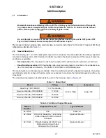
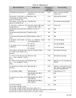
Table 2–3 Safety Devices
Unsafe Conditions
Safety Device
Automatic re-
start with
fault cleared
Device setting
1 Excessive drop in pressure
Automatic reset of low pres-
sure switch
YES
Cutout: -2.9 psig (-0.2 Bar)
Timer 5 min
2 Excessive current draw on all
microprocessor outputs (evapo-
rator and condenser fan)
Electronic relay
YES
Self-protected opening
3 Excessive current draw com-
pressor or standby motor
Overload relay
YES
See electrical wiring diagram
4 Excessive compressor dis-
charge pressure
Automatic reset of High pres-
sure switch (HP1, HP3)
YES
Timer 5 min
5 Excessive current draw unit on
standby
Standby fuse (FS)
(a)
NO
50A
6 Excessive current draw unit on
road
Road fuse (FR)
NO
50A
7 Excessive current draw unit on
road
Main Road fuse (FR1)
(b)
NO
50A
8 Excessive current draw con-
trol circuit
Fuse on electronic board
(Field Replaceable)
(c)
NO
1A (Time Delayed)
9 Connection error on primary
transformer
F1 115/1/60
NO
8A (Time Delayed)
F1 230/1/60
5A (Time Delayed)
F1 230/3/60
10 Excessive compressor motor
or standby motor winding tem-
perature
Internal Thermal Overload
YES
Self-protected opening
11 Clutch not functioning prop-
erly - road (excessive current
draw)
Electronic relay
YES
Self-protected opening
12 Clutch not functioning prop-
erly - road (insufficient current
draw)
Electronic relay
YES
Detection of min. threshold at
750 mA
13 Double power supply (road +
standby)
Microprocessor
YES
Display on Cab Command until
one of the 2 power supplies
have been disconnected.
14 Low battery voltage
Microprocessor
YES
Cutout/cut-in at 10 V
15 Excess current draw of AC
circuits
Main Standby Fuse Block
(FB) 115/1/60
YES
25A
Main Standby Fuse Block
(FB) 230/1/60
16A
Main Standby Fuse Block
(FB) 230/3/60
12A
16 Excess CFM Amp.
NO
30A
(a) On road / standby unit only
(b) This fuse is located close to the vehicle battery (12 V).
(c) This fuse is located on the logic board inside the microprocessor and protects the
microprocessor against reverse polarity on the power supply.
Summary of Contents for Integra 35X
Page 2: ......
Page 8: ......
Page 12: ......
Page 68: ......
Page 69: ...wiring schematics ...
Page 70: ......
Page 71: ...wiring schematics ...
Page 72: ......
Page 73: ...wiring schematics ...
Page 74: ......
Page 75: ...wiring schematics ...
Page 76: ......
Page 79: ......

