62-12023
2-10
2.8
Refrigerant Circuit
2.8.1
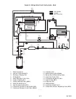
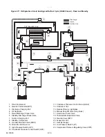
Refrigerant Circuit During Cooling
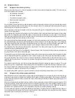
When cooling (See
), the unit operates as a vapor compression refrigeration system. The main compo-
nents of the system are as follows:
• Reciprocating compressor
• Air-cooled condenser
• Thermostatic expansion valve
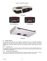
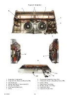
• Direct expansion evaporator
• Hot gas solenoid
The compressor raises the pressure and temperature of the refrigerant, and forces it through the discharge check
valve and condenser pressure control valve into the condenser tubes. The discharge check valves prevent reverse
flow through the non operating compressor.
When operating on the road compressor, the flow also passes through an oil separator where oil is removed and
returned to the compressor.
The condenser fan circulates surrounding air over the outside of the condenser tubes. Heat transfer is thus estab-
lished from the refrigerant gas (inside the tubes) to the condenser air (flowing over the tubes). The condenser
tubes have fins designed to improve the transfer of heat. This removal of heat causes the refrigerant to liquefy. Liq-
uid refrigerant flows from the condenser to the receiver.
The receiver stores the additional charge necessary for low ambient operation, and for heating and defrost modes.
The refrigerant leaves the receiver and flows through a manual receiver shut-off valve (king valve). The refrigerant
then flows through the filter drier, where an absorbent keeps it dry and clean, and then through a sight glass. The
sight glass is fitted with an indicator that changes color to indicate moisture content of the refrigerant.
The refrigerant then flows through the liquid line check valve. The check valve serves to prevent reverse flow of
refrigerant during the heating/defrost cycle.
The refrigerant then flows to the “Liquid/Suction” heat exchanger. Here, the liquid is further reduced in temperature
by giving off some of its heat to the suction gas.
The liquid than enters the thermostatic expansion valve (with external pressure equalizer) which regulates the flow
rate of refrigerant towards the evaporator in order to obtain maximum use of the evaporator heat transfer surface.
The evaporator tubes have aluminum fins to increase heat transfer; therefore heat is removed from the air circu-
lated through the evaporator. This cold air is circulated throughout the truck to maintain the cargo at the desired
temperature.
The transfer of heat from the air to the low temperature liquid refrigerant causes the liquid to vaporize. The vapor
passes through the “Liquid/Suction” heat exchanger where it absorbs more heat from the high temperature liquid.
The vapor at enters the compressor pressure regulating valve (CPR) which regulates refrigerant pressure entering
the compressor to prevent overloading of the compressor.
The quench valve (BPV) opens as required to maintain a maximum discharge temperature of 127°C (260°F).
2.8.2
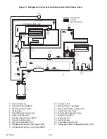
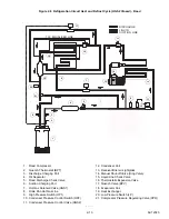
Refrigerant Circuit During Heat And Defrost
When refrigerant vapor is compressed to a high pressure and temperature in a compressor, the mechanical energy
necessary to operate the compressor is transferred to the gas as it is being compressed. This energy is referred to
as the “heat of compression” and is used as the source of heat during the heating or defrost cycle (See
and
).
When the microprocessor activates heating or defrost, the hot gas solenoid valve (HGS1) energizes (opens). If the
condenser pressure control switch (HP2) is open, the condenser pressure control valve (HGS2) energizes to close
the line to the condenser. If pressure rises to the cut-in setting of HP2 (See
), HGS2 de-energizes to
pressurize the condenser and force more refrigerant into the circuit, increasing heating capacity.
The main difference between heating and defrosting is that when in heating mode the evaporator fans continue to
run circulating the air throughout the truck to heat the product. When defrosting, the evaporator fans stop, allowing
the heated vapor to defrost any ice build-up on the coil.
Summary of Contents for Integra 35X
Page 2: ......
Page 8: ......
Page 12: ......
Page 68: ......
Page 69: ...wiring schematics ...
Page 70: ......
Page 71: ...wiring schematics ...
Page 72: ......
Page 73: ...wiring schematics ...
Page 74: ......
Page 75: ...wiring schematics ...
Page 76: ......
Page 79: ......


