2-13
62-12023
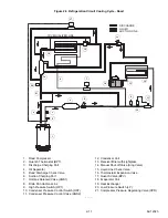
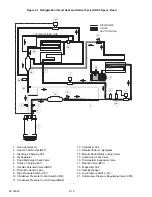
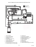
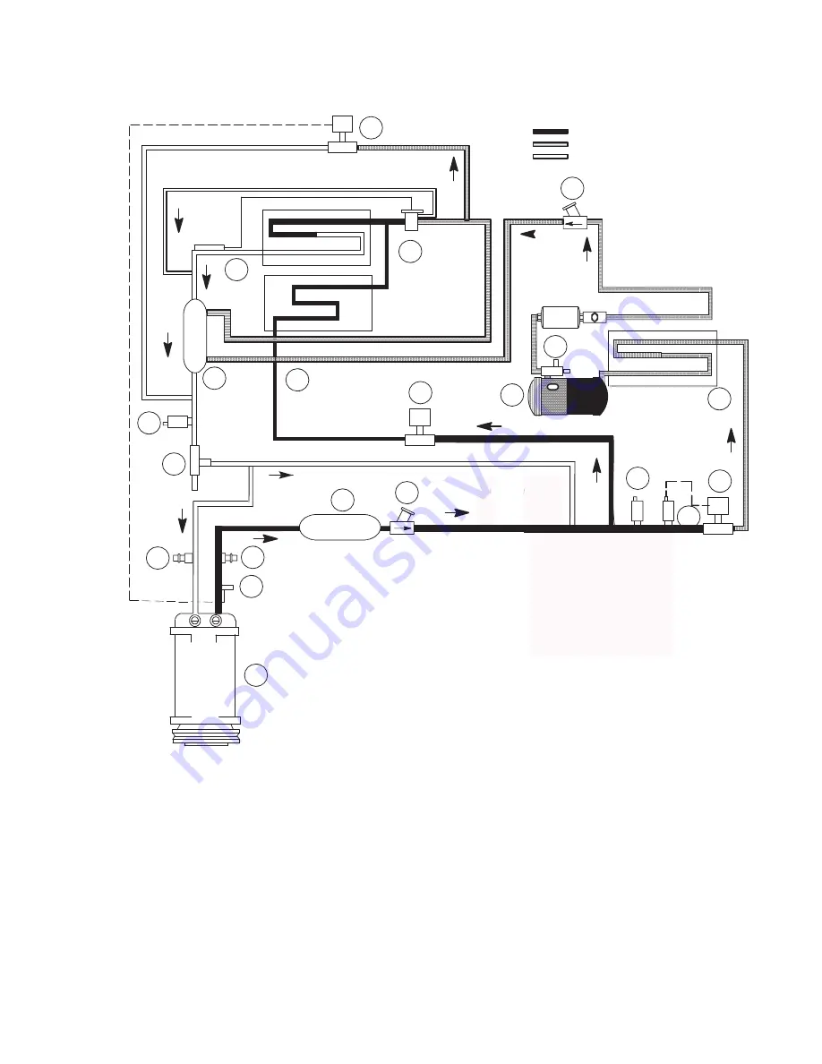
Figure 2.8 Refrigeration Circuit Heat and Defrost Cycle (HGS2 Closed) - Road
1. Road Compressor
2. Quench Thermostat (BPT)
3. Discharge Charging Port
4. Oil Separator
5. Road Discharge Check Valve
6. Suction Charging Port
7. Hot Gas Solenoid Valve (HGS1)
8. Drain Pan Hot Gas Line
9. High Pressure Switch (HP1)
10. Condenser Pressure Control Switch (HP2)
11. Condenser Pressure Control Valve (HGS2)
12. Condenser Coil
13. Receiver/Drier w/ sightglass
14. Manual Shut-off Valve (King Valve)
15. Liquid Line Check Valve
16. Thermostatic Expansion Valve
17. Quench Valve (BPV)
18. Evaporator Coil
19. Heat Exchanger
20. Low Pressure Switch (LP)
21. Compressor Pressure Regulating Valve (CPR)
- - - - -
TXV EQUALIZER LINE
DISCHARGE
LIQUID
SUCTION LINE
11
22
33
44
55
66
77
88
99
10
10
11
11
12
12
13
13
14
14
15
15
16
16
17
17
18
18
19
19
20
20
21
21
Summary of Contents for Integra 35X
Page 2: ......
Page 8: ......
Page 12: ......
Page 68: ......
Page 69: ...wiring schematics ...
Page 70: ......
Page 71: ...wiring schematics ...
Page 72: ......
Page 73: ...wiring schematics ...
Page 74: ......
Page 75: ...wiring schematics ...
Page 76: ......
Page 79: ......

