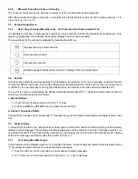
3-7
62-12023
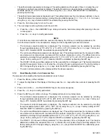
If the unit is to be operated in the standby mode, connect power as follows:
1. Check that the external power source corresponds to the characteristics of the unit (see
). The
external power source circuit breaker must be open.
2. The unit must be turned OFF by pressing the OFF button on the Cab Command Two.
3. Plug the power cord into unit receptacle.
4. Close external power source circuit breaker.
3.2.5
Start-Up Process
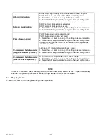
Start-up on Road with cool setpoint and box temp > -5°F (-20.6°C):
a. 0 time: ON key pushed
b. 20 seconds: HGS1 ON (pressure equalization)
c. 40 seconds: CLHR ON (Road clutch)
d. 50 seconds: HGS1 OFF/ fans ON (unit in cool)
Start-up on Standby with cool setpoint and box temp > -5°F (-20.6°C):
a. 0 time: ON key pushed
b. 15 seconds: HGS1 ON (pressure equalization)
c. 40 seconds MC ON (Standby contactor coil)
d. 50 seconds: HGS1 OFF/ fans ON (unit in cool)
Start-up on Road with heat setpoint and box temp > -5°F (-20.6°C):
a. 0 time: ON key pushed
b. 20 seconds: HGS1/ HGS2/ CLHR ON
c. 45 seconds: fans/ BPV ON (unit in heat)
Start-up on Standby with heat setpoint and box temp > -5°F (-20.6°C):
a. 0 time: ON key pushed
b. 10 seconds: HGS1/ HGS2 ON
c. 20 seconds: MC/ fans/ BPV ON (unit in heat)
Start-up on Road with cool setpoint and box temp < -5°F (-20.6°C):
a. 0 time: ON key pushed
b. 20 seconds: CLHR / fans ON (unit in cool)
Start-up on Standby with cool setpoint and box temp < -5°F (-20.6°C):
a. 0 time: ON key pushed
b. 10 seconds: MC/ fans ON (unit in heat)
Start-up on Standby with heat setpoint and box temp < -5°F (-20.6°C):
a. 0 time: ON key pushed
b. 10 seconds: HGS1/ HGS2/ MC ON
c. 15 seconds: fans/ BPV ON (unit in heat)
Start-up on Road with heat setpoint and box temp < -5°F (-20.6°C):
a. 0 time: ON key pushed
b. 20 seconds: HGS1/ HGS2/ CLHR ON
Summary of Contents for Integra 35X
Page 2: ......
Page 8: ......
Page 12: ......
Page 68: ......
Page 69: ...wiring schematics ...
Page 70: ......
Page 71: ...wiring schematics ...
Page 72: ......
Page 73: ...wiring schematics ...
Page 74: ......
Page 75: ...wiring schematics ...
Page 76: ......
Page 79: ......

