3-9
62-12023
3.5.2
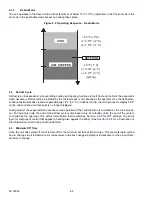
Low Battery Voltage Alarms
There is a 40 second time delay during start-up. After this delay if the battery voltage drops below 10.5V ±0.5V, the
microprocessor will react 20 seconds later and the unit will go out of temperature control mode. The microproces-
sor will check the voltage after another 20 seconds. If battery voltage still has not risen, the unit will remain out of
temperature control mode for another 10 minutes, the battery alarm will be activated and the Cab Command will
display the message “bAt”. Unit will return to temperature control mode if battery voltage has risen after 10minutes.
If the battery voltage has not risen after this 10 minute period the unit will remain out of temperature control mode
another two minutes and the microprocessor will check the battery voltage every two minutes. Unit will return to
temperature control mode in its current configuration when battery voltage rises to 10.5V ±0.5V.
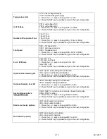
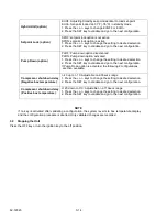
Table 3–1 Alarm Messages
Road Only
Standby
Alarm Codes
Description
X
X
A00
Red LED flashes
No alarm
Unit in operation
X
A01/A02
High or Low pressure switch
X
A01
Low pressure switch (LP)
X
A02
High pressure switch
X
A03
Standby compressor thermal overload open
X
X
A04
Road compressor clutch (CLHR) not functioning properly
X
A05
Standby contactor (MC) high amp draw
X
X
A06
Condenser fan motor (CFM) high amp draw
X
X
A07
Evaporator Fan low rotational speed
A08
(Not applicable)
X
X
A09
Hot gas valve (HGS1) high amp draw
X
X
A10
Quench valve (BPV) high amp draw
X
X
A11
Condenser pressure control valve (HGS2) high amp draw
X
X
A12
High temperature alarm
X
X
A13
Low temperature alarm
X
X
A14
Defrost cycle is greater than 45 minutes
X
X
A15
Setpoint adjusted out of the range -20.2 to 86°F (-29°C/+30°C) or
below the programmed low threshold
X
A16
Evaporator drain line heater (DWR) not functioning properly
(option)
X
A17
Transformer/Rectifier thermal overload (RBT) open
X
A18
Control fault, electric heat (option)
X
A20
Low pressure switch jumper (microprocessor terminal 6 to SP2) open
X
A21
Compressor contactor (MC) open circuit
X
A22
Condenser fan motor (CFM) open circuit
X
A23
Hot water solenoid valve (HWV) open circuit (option)
X
A24
Hot gas valve (HGS1) open circuit
X
A25
Quench valve (BPV) open circuit
X
A26
Condenser Pressure Control Valve (HGS2) open circuit
X
A27
Evaporator drain line heater (DWR) open circuit (option)
Summary of Contents for Integra 35X
Page 2: ......
Page 8: ......
Page 12: ......
Page 68: ......
Page 69: ...wiring schematics ...
Page 70: ......
Page 71: ...wiring schematics ...
Page 72: ......
Page 73: ...wiring schematics ...
Page 74: ......
Page 75: ...wiring schematics ...
Page 76: ......
Page 79: ......

