62-12023
3-10
3.5.3
Clearing Past Alarm Messages
The alarm list provides information on current alarms and past alarms which may be helpful in trouble shooting unit
problems. Once all the alarm information has been noted and service is complete, the alarm list may be cleared.
a. To clear the past alarm messages:
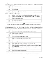
1. Press the ON, the + and the - keys at the same time.
b. To clear the active alarm messages:
1. Turn unit OFF and then back ON.
3.6
Checking the EPROM Version
1. Press the Unit start-up key to turn on the unit.
2. Press the SET key for five seconds.
3. Press the SET key again to display EPROM version number.
4. Press the SET key again to return to the normal display of box temperature.
3.7
Modification of Functional Parameters
3.7.1
Road Only Units - Cab Command
The procedure for adjusting the functional parameters is as follows:
1. The temperature display is selectable between Fahrenheit and Celsius. Units are configured for Celsius
from the factory. To set the display to Fahrenheit, the selection jumper must be removed and discarded.
2. Press the Unit shut-down key to turn off the unit.
3. The following steps must be performed with the unit OFF:
a. Hold both DEFROST and ON keys momentarily in order to display parameters.
b. Use the + and - keys to modify parameters as needed.
c. Press the SET key to confirm a change.
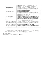
NOTE
If no buttons are depressed within five seconds of pressing the DEFROST and ON keys or modifying
parameters, the Cab Command reverts to box temperature display and the configuration procedure is
aborted.
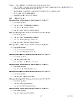
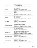
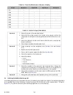
X
A28
Relay fault, electric heat (option)
X
A45
EPROM Failure
X
X
BAT
Low battery voltage
X
2EP
Functional parameters have not been set or have been lost. Press
and hold the SET key to clear the alarm. Refer to Section 2.7.1 to
set parameters.
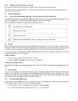
X
X
EE
Probe not functioning properly or evaporator temperature out of
limits [-49° to 174°F (-45° to 79°C)]
X
X
Err
Programming error on part of operator
X
X
---
Setpoint lower than maximum setpoint but in the range of -20°F to
86°F.
X
---
---
---
Dual power supply (road and standby units only - Cab Command
Two)
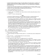
Table 3–1 Alarm Messages (Continued)
Road Only
Standby
Alarm Codes
Description
Summary of Contents for Integra 35X
Page 2: ......
Page 8: ......
Page 12: ......
Page 68: ......
Page 69: ...wiring schematics ...
Page 70: ......
Page 71: ...wiring schematics ...
Page 72: ......
Page 73: ...wiring schematics ...
Page 74: ......
Page 75: ...wiring schematics ...
Page 76: ......
Page 79: ......

