3-11
62-12023
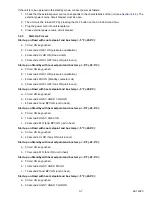
• The defrost duration parameter is displayed. This setting determines the length of time in minutes the unit
will remain in defrost once defrost is initiated. The defrost duration can be selected by scrolling through
available options (10, 20, 25, 30 or 45 minutes) using the (+) or (-) keys. Selection MUST be validated by
pressing the SET key.
• The defrost interval parameter is displayed next. This setting determines the time between defrosts in hours.
The defrost interval can be selected by scrolling through available options (0, 1, 1.5, 2, 2.5, 3, 4, 5, 6 hours)
using the (+) or (-) keys. Selection MUST be validated by pressing the SET key.
4. Press the Unit start-up key to turn on the unit.
5. The next steps must be performed with the unit ON:
a. Press the +, then -, then DEFROST keys. All keys should be held momentarily after pressing in the cor-
rect sequence.
b. Press the + or - keys to modify parameters.
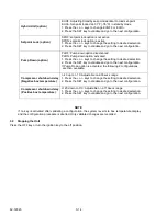
NOTE
If no buttons are depressed within five seconds of pressing the ON key or modifying parameters, the
Cab Command reverts to box temperature display and the configuration procedure is aborted.
• The minimum setpoint parameter is displayed. The minimum setpoint can be selected by scrolling
through available options [-20°F (-28.9°C), -4°F (-20°C), 32°F (0°C)] using the (+) or (-) keys. Factory set-
ting is -20°F. Selection MUST be validated by pressing the SET key.
• The null mode differential temperature is displayed next. This setting determines the temperature differ-
ence between box temperature and setpoint that controls compressor cycling. The differential can be
selected by scrolling through available options [1.8°F (1°C), 3.6°F (2°C), or 5.4°F (3°C)] using the (+) or (-
) keys. Factory setting is 3.6°F (2°C). Selection MUST be validated by pressing the SET key.
• The ON/OFF (Continuous airflow) parameter for the evaporator fan is displayed next. This feature determines
whether the evaporator fan is on or off when the unit cycles off upon reaching setpoint. The factory setting is
OFF. Change setting by using the (+) or (-) keys. Selection MUST be validated by pressing the SET key.
• The return air temperature will be displayed after the above sequence.
3.7.2
Road/Standby Units - Cab Command Two
The procedure for adjusting the functional parameters is as follows:
1. Press the ON key of the controller.
2. To adjust the brightness of the display at this time, press the + or - keys within five seconds of pressing the ON
key.
3. Press and hold the +, -, and then DEFROST keys n the correct sequence.
4. Press the + or - keys to modify parameters.
5. Press the SET key to confirm a change. The display will return to box temperature.
• The minimum setpoint parameter is displayed. The minimum setpoint can be selected by scrolling
through available options [-20.2°F (-29°C), 68°F (20°C), 32°F (0°C)] using the (+) or (-) keys. Factory set-
ting is -20°F. Selection MUST be validated by pressing the SET key.
• The maximum setpoint parameter is displayed. The maximum setpoint can be selected by scrolling
through available options [68°F (20°C), 86°F (30°C)] using the (+) or (-) keys. Factory setting is 68°F.
Selection MUST be validated by pressing the SET key.
• The null mode differential temperature is displayed next. This setting determines the temperature differ-
ence between box temperature and setpoint that controls compressor cycling. The differential can be
selected by scrolling through available options [1.8°F (1°C), 3.6°F (2°C), or 5.4°F (3°C)] using the (+) or (-
) keys. Factory setting is 3.6°F (2°C). Selection MUST be validated by pressing the SET key.
• The ON/OFF (Continuous airflow) parameter for the evaporator fans is displayed next. This feature
determines whether the evaporator fan is on or off when the unit cycles off upon reaching setpoint. The
factory setting is OFF. Change setting by using the (+) or (-) keys. Selection MUST be validated by press-
ing the SET key.
Summary of Contents for Integra 35X
Page 2: ......
Page 8: ......
Page 12: ......
Page 68: ......
Page 69: ...wiring schematics ...
Page 70: ......
Page 71: ...wiring schematics ...
Page 72: ......
Page 73: ...wiring schematics ...
Page 74: ......
Page 75: ...wiring schematics ...
Page 76: ......
Page 79: ......

