62-12023
5-4
CAUTION
!
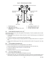
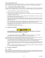
To prevent trapping liquid refrigerant in the manifold gauge set be sure set is brought to suc-
tion pressure before disconnecting.
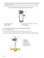
3. Backseat the low side service valve. Frontseat both manifold set hand valves. Remove the refrigeration
hoses from the access valves.
4. Install both service valve stem caps (finger-tight only).
5.3
Pumping Down or Removing the Refrigerant Charge
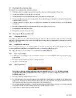
CAUTION
!
When working with refrigerant use safety glasses and gloves to avoid burns. Hoses and cop-
per tubing can be hot when unit is running.
NOTE
Once the system is open, it must be evacuated and dehydrated (see
).
NOTE
To avoid damage to the earth’s ozone layer, use a refrigerant recovery system whenever removing
refrigerant.
Pumping the Unit Down
To service the expansion valve, CPR valve or evaporator coil, pump most of refrigerant into condenser
coil and
receiver as follows:
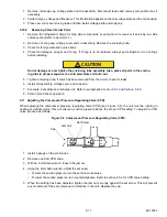
1. Backseat suction and discharge service valve (turn counterclockwise) to close off gauge connection, and
attach manifold gauges to valves.
2. Open valves two turns (clockwise). Purge gauge line.
3. Close the receiver outlet (king) valve by turning clockwise. Start unit and run in high speed cooling. Place
Run-stop switch in the STOP position when unit reaches 0.1 kg/cm
2
(1 psig).
4. Frontseat (close) suction service valve and the refrigerant will be trapped between the compressor suction
service valve and the manual shutoff (King) valve.
5. Before opening up any part of the system, a slight positive pressure should be indicated on the pressure gauge.
6. When opening up the refrigerant system, certain parts may frost. Allow the part to warm to ambient tempera-
ture before dismantling. This avoids internal condensation which puts moisture in the system.
7. When service has been completed. Open (backseat) King valve and midseat suction service valve.
8. Leak check connections with a leak detector (refer to
9. Start the unit in cooling and check for noncondensibles.
10. Check the refrigerant charge (refer to
NOTE
Store the refrigerant charge in an evacuated container if the system must be opened between the
compressor discharge valve and receiver.
NOTE
Whenever the system is opened, it must be evacuated and dehydrated (refer to section
Summary of Contents for Integra 35X
Page 2: ......
Page 8: ......
Page 12: ......
Page 68: ......
Page 69: ...wiring schematics ...
Page 70: ......
Page 71: ...wiring schematics ...
Page 72: ......
Page 73: ...wiring schematics ...
Page 74: ......
Page 75: ...wiring schematics ...
Page 76: ......
Page 79: ......


