5-7
62-12023
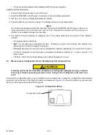
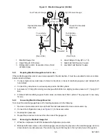
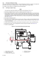
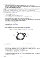
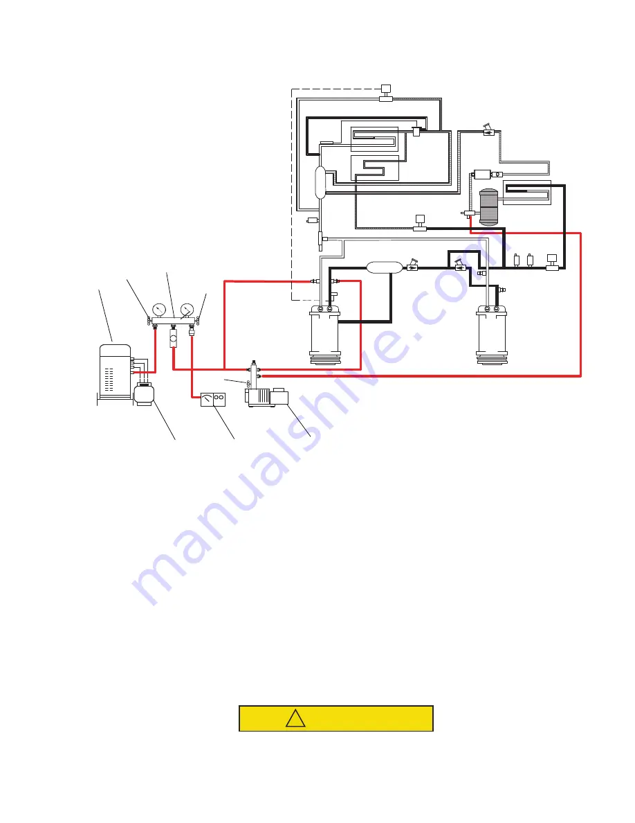
Figure 5.2 Vacuum Pump Connection
1. Refrigerant Recovery Unit
2. Suction Valve (Low Side)
3. Manifold Gauge Set
4. Discharge Valve (High Side)
5. Refrigerant Cylinder
6. Electronic Vacuum Gauge
7. Vacuum Pump Valve
8. Vacuum Pump
- - - - -
7.
Remove refrigerant using a refrigerant recovery system.
8.
Repeat steps 5 to 7.
9.
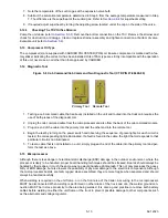
Evacuate unit to 500 microns. Close off
vacuum pump valve and stop pump.Wait five minutes to see if
vacuum holds. This checks for residual mois-ture and/or leaks.
10.
With a vacuum still in the unit, the refrigerant charge may be drawn into the system from a refrigerant con-
tainer on weight scales. See
for correct charge. Continue to
5.6
Charging the Refrigeration System
CAUTION
!
Refrigerant R-404A is a blend. Charging as a vapor will change the properties of the refrigerant.
Only liquid charging through the king valve is acceptable.
5
Summary of Contents for Integra 35X
Page 2: ......
Page 8: ......
Page 12: ......
Page 68: ......
Page 69: ...wiring schematics ...
Page 70: ......
Page 71: ...wiring schematics ...
Page 72: ......
Page 73: ...wiring schematics ...
Page 74: ......
Page 75: ...wiring schematics ...
Page 76: ......
Page 79: ......


