62-12023
5-10
5. Open cylinder valve. While observing indicator (light or meter), slowly close bleed-off valve and increase
pressure until the switch opens or closes. Slowly open bleed-off valve (to decrease pressure) until switch
reverts to normal position.
6. If switch does not activate within tolerances provided, replace switch. Test new switch before installation.
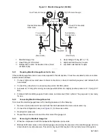
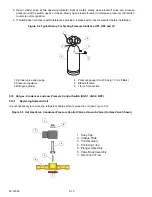
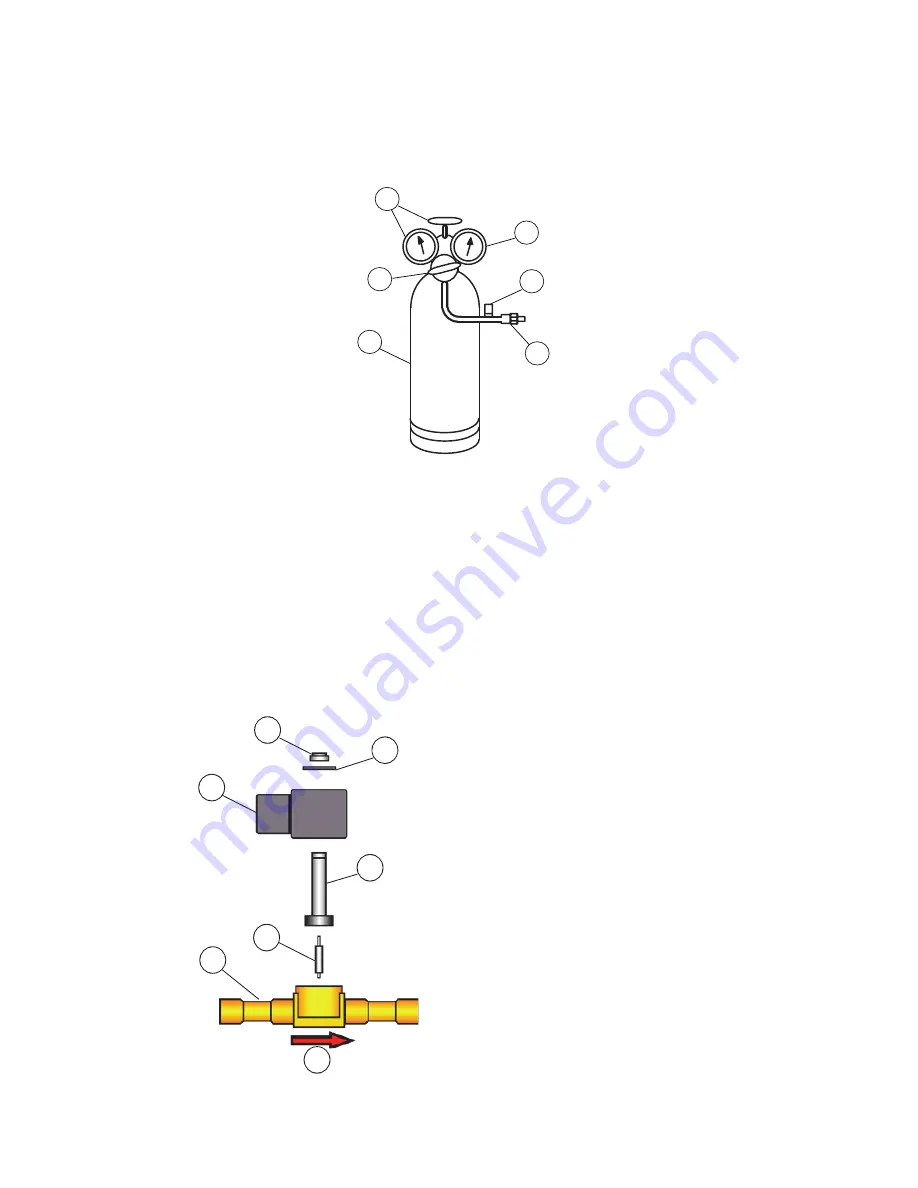
Figure 5.4 Typical Setup For Testing Pressure Switches HP1, HP2 and LP
1.Cylinder valve and gauge
2.Pressure regulator
3.Nitrogen cylinder
4. Pressure gauge (0 to 400 psig = 0 to 28 Bars)
5. Bleed-off valve
6. 1/4 inch connection
- - - - -
5.10 Hot gas, Condenser, and Low Pressure Control Switch (HGS1, HGS2, BPV)
5.10.1
Replacing Solenoid Coil
It is not necessary to remove the refrigerant charge when replace the coil (see
).
Figure 5.5 Hot Gas Valve, Condenser Pressure Control Valve or Quench Valve (Hot Gas Valve Shown)
1
1
2
2
3
3
4
4
5
5
6
6
11
222
33
44
55
66
77
1. Snap Cap
2. Voltage Plate
3. Coil Assembly
4. Enclosing Tube
5. Plunger Assembly
6. Valve Body Assembly
7. Direction of Flow
Summary of Contents for Integra 35X
Page 2: ......
Page 8: ......
Page 12: ......
Page 68: ......
Page 69: ...wiring schematics ...
Page 70: ......
Page 71: ...wiring schematics ...
Page 72: ......
Page 73: ...wiring schematics ...
Page 74: ......
Page 75: ...wiring schematics ...
Page 76: ......
Page 79: ......

