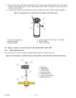
5-11
62-12023
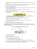
1. Remove coil snap cap, voltage plate and coil assembly. Disconnect leads and remove coil junction box if
necessary.
2. Verify coil type, voltage and frequency. This information appears on the coil voltage plate and the coil housing.
3. Place new coil over enclosing tube and then install voltage plate and snap cap.
5.10.2
Replacing Valve Internal Parts
1. Remove the refrigerant charge for high side components or pump down to receiver if servicing low side
components. (Refer to
).
2. Remove coil snap cap, voltage cover and coil assembly. Remove the enclosing tube.
3. Check for foreign material in valve body.
4. Check for damaged plunger and O-ring. If O-ring is to be replaced, always put refrigerant oil on O-rings
before installing.
CAUTION
!
Do not damage or over tighten the enclosing tube assembly. Also, place all parts in the enclos-
ing tube in proper sequence to avoid premature coil burn-out.
5. Tighten enclosing tube. If valve has been removed from the circuit, check for leaks.
6. Install coil assembly, voltage cover and snap cap.
7. Evacuate, dehydrate and recharge unit. Refer to paragraphs
and
.
8. Start unit and check operation.
5.11 Adjusting the Compressor Pressure Regulating Valve (CPR)
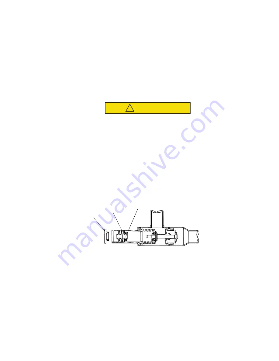
When adjusting the compressor pressure regulating valve (CPR) (see
), the unit must be running in
heating or defrost mode. This will ensure a suction pressure above the proper CPR setting. To adjust the CPR
valve, proceed as follows:
Figure 5.6 Compressor Pressure Regulating Valve (CPR)
1. Install a gauge on the suction line.
2. Remove cap from CPR valve.
3. With an 8 mm Allen wrench, loosen the jam nut.
4. Using the 8mm Allen wrench, adjust the set screw.
• To raise the suction pressure turn the set screw clockwise
• To lower the suction pressure, turn counterclockwise. Refer to
section
2
.5.2 for CPR valve setting.
5. When the setting has been adjusted, tighten the jam nut securely against the set screw. This will prevent
any movement of the set screw due to vibrations in the unit. Replace the cap.
Cap
Jam Nut
Set Screw
Summary of Contents for Integra 35X
Page 2: ......
Page 8: ......
Page 12: ......
Page 68: ......
Page 69: ...wiring schematics ...
Page 70: ......
Page 71: ...wiring schematics ...
Page 72: ......
Page 73: ...wiring schematics ...
Page 74: ......
Page 75: ...wiring schematics ...
Page 76: ......
Page 79: ......

