62-12023
5-12
5.12 Thermostatic Expansion Valve
MOP expansion valve characteristics:
• In order to avoid compressor overcharge, an MOP expansion valve (with limited flow) is used.
• Operating: the expansion valve will not open more than the MOP setpoint. Any temperature increase at the
bulb should not open the expansion valve further.
The thermal expansion valve is an automatic device which maintains constant superheat of the refrigerant gas
leaving the evaporator regardless of suction pressure. The valve functions are: (a) automatic response of refriger-
ant flow to match the evaporator load and (b) prevention of liquid refrigerant entering the compressor.
Unless the valve is defective, it requires no adjustment, but maintenance must be done every year in order to clean
the orifice strainer. Refer to
.
5.12.1
Replacing Expansion Valve
1. Pump the unit down. Refer to paragraph
2. Remove insulation from expansion valve bulb and then remove bulb from suction line.
3. Loosen inlet nut and unbraze equalizer line and outlet line from expansion valve.
4. The thermal bulb is located below the center of the suction line. This area must be clean to ensure positive
bulb contact. Strap thermal bulb to suction line and insulate both.
5. Braze the equalizer tubes to expansion valve.
6. Evacuate, dehydrate and recharge unit.
7. Check superheat (refer to
).
5.12.2
Measuring Superheat
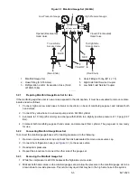
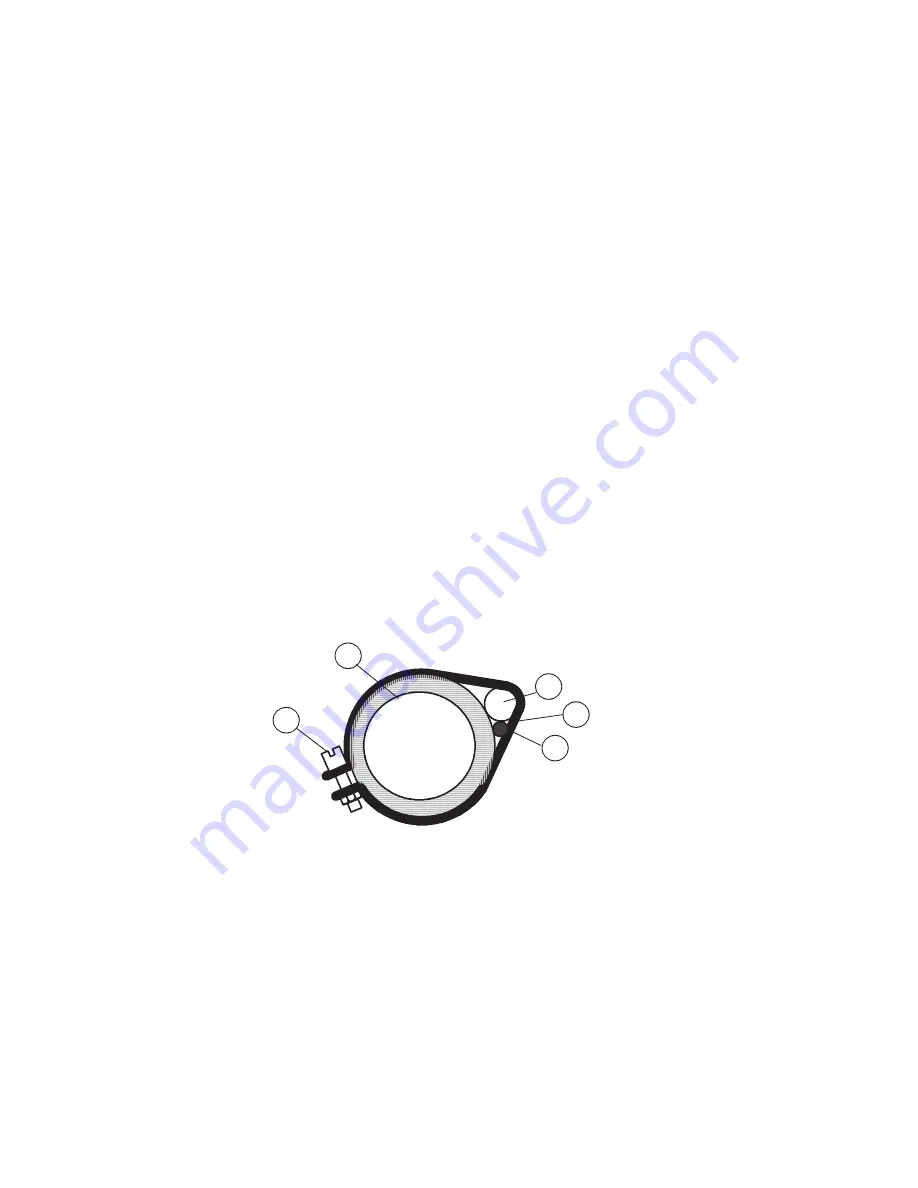
1. Remove insulation from expansion valve bulb and suction line. See
.
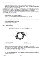
Figure 5.7 Thermostatic Expansion Valve Bulb And Thermocouple
1. Suction Line (end view)
2. TXV Bulb Clamp
3. Thermocouple
4. TXV Bulb
5. Nut and Bolt (Clamp)
- - - - -
2. Loosen one TXV bulb clamp and check that the area under clamp (above TXV bulb) is clean.
3. Place thermocouple above (parallel to) the TXV bulb and then secure loosened clamp making sure both
bulbs are firmly secured to suction line as shown in
4. Connect an accurate gauge to the ¼” port on the suction service valve.
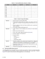
5. Run unit until stabilized at -4°F (-20°C) box temperature.
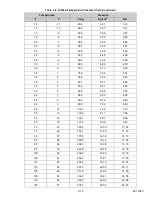
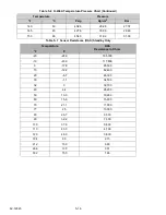
6. From the temperature/pressure chart (
), determine the saturation temperature corresponding to
the evaporator outlet pressure.
11
22
33
44
55
Summary of Contents for Integra 35X
Page 2: ......
Page 8: ......
Page 12: ......
Page 68: ......
Page 69: ...wiring schematics ...
Page 70: ......
Page 71: ...wiring schematics ...
Page 72: ......
Page 73: ...wiring schematics ...
Page 74: ......
Page 75: ...wiring schematics ...
Page 76: ......
Page 79: ......

